Ethernet indicator led's – Watlow EZ-ZONE RMA Modul User Manual
Page 57
Watlow EZ-ZONE
®
RMA Module
•
54
•
Chapter 7 RMA Communications
Application Note:
Assume that in the following graphic there are 4 RMC
modules on the network with each having 4 instances
of an Analog Input. If it is desired to access all of the
Analog Inputs from each module the CIP offset must,
at a minimum, have an offset of 4 between each mod-
ule (gateway instance). If the offset for each module is
set as shown on the following page, the 4th instance
would not be available. As another example, looking
at the RMC User's Guide in the Setup Page under the
Variable Menu, it shows that there are 8 instances
available. If all 8 for each module are to be made
available to the Master (OIT, PC, PLC) then the off-
sets should at a minimum be set as shown below:
RM1 = 0, RM2 = 9, RM3 = 18 and RM4 = 27
Using the RMC User's Guide look at the Operations
Page and then the Analog Input Menu. There you
will find the class, instance and attribute of the first
instance of the Analog Input Value for RM 2 to be
the following:
Class = 104 or (0x68)
Instance =
5
Attribute = 1
This information would be needed to execute an ex-
plicit message to read this parameter. Notice that the
instance above is identified as 5 and not 1 as listed
in the RMC documentation. The CIP offset is always
added to the documented instance. Using the follow-
ing graphic the offset entries are listed below.
1. RUI prompt entry for gateway instance 1 (RM 1)
follows: [`oSt] = 0
RUI prompt entry for gateway instance 2 (RM 2) fol-
lows: [`oSt] = 4
RUI prompt entry for gateway instance 3 (RM 3) fol-
lows: `oSt] = 8
RUI prompt entry for gateway instance 4 (RM 4) fol-
lows: [`oSt] = 12
Likewise, to read the Analog Input Value instance 2
of RM 4 the following information would need to be
entered in the message instruction:
Class = 104 or (0x68)
Instance =
14
or (0x0E)
Attribute = 1
[ao;nb]
CIP Implicit Output (Produced) Assembly
Size, used exclusively when communicating
implicitly. For any given RMA gateway in-
stance (1 - 17), the output assembly size will
never be greater than 40, 32 bit members.
The user entry ranges from 0 to 40.
[ai;nb]
CIP Implicit Input (Consumed) Assembly
Size, used exclusively when communicating
implicitly. For any given RMA gateway in-
stance (1 - 17), the input assembly size will
never be greater than 40, 32 bit members.
The user entry ranges from 0 to 40.
Note:
When configuring the RMA assemblies for each gate-
way instance it is important to note that the maxi-
mum number of implicit input/output members using
EtherNet/IP cannot exceed 100. A network could have
up to 5 EZ-ZONE controllers with 20 members each
maximum or the 100 members can be divided any way
the user would like as long as 40 I/O members per
module are not exceeded.
Using the graphic above as an example, if:
[Gtw]
instance 1 has [ai;nb] and [ao;nb] set to 5
[Gtw]
instance 2 has [ai;nb] and [ao;nb] set to 5
[Gtw]
instance 3 has [ai;nb] and [ao;nb] set to 5
[Gtw]
instance 4 has [ai;nb] and [ao;nb] set to 5
Each of the four RM modules will contain the first
5 members of the I/O assembly and this information
would then be passed implicitly to the Master on the
EtherNet/IP network.
Note:
In the above graphic there are several prompts omit-
ted for the sake of saving some space. When the
Ethernet addressing mode is set to Fixed the user
will find several more prompts that will follow the
prompts shown for "Ethernet Addressing Mode" relat-
ed to specifying the actual IP [ip;f1] - [ip;f4], subnet
[ip;s1]
- [ip;s4] and the gateway [ip;g1] - [ip;g4]
(external gateway) addresses. If set to receive an IP
address from a host [dhCp] computer, the prompts
shown are accurate.
Note
:
When changing the RMA IP address, power must be
cycled for the new address to take affect.
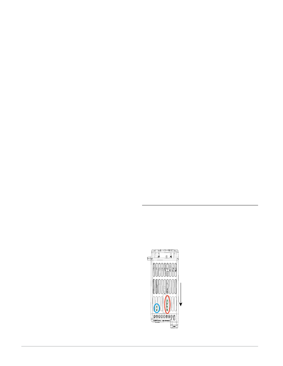
Ethernet Indicator LED's
The RMA has four indicator LED's on the top of the
module for Ethernet, two of which are not used for
Modbus TCP. The Module Status and Network Sta-
tus LED’s apply only when EtherNet/IP is enabled.
The characteristics of the Activity and Link indicator
LED’s are defined in the Ethernet specification.
This is a view of the RMA module
looking down into the top where
the arrow is pointing towards the
front of the module.
Left Front (
blue
circle):
- Green accessing SD card.
- Red accessing internal memory
Left Rear (
blue
circle):
- Flashing green heartbeat
- Red boot loader activity
Right, from front to rear (
red
circle):
- Active Status - Ethernet
- Link Status - Ethernet
- MS (Module Status - CIP)
- NS (Network Status - CIP)