Watlow EZ-ZONE RMA Modul User Manual
Page 22
Watlow EZ-ZONE
®
RMA Module
•
19
•
Chapter 2 Install and Wire
Conventions Used in the Menu Pages
To better understand the menu pages that follow
review the naming conventions used. When encoun-
tered throughout this document, the word "default"
implies as shipped from the factory. Each page (Op-
erations, Setup and Factory) and their associated
menus have identical headers defined below:
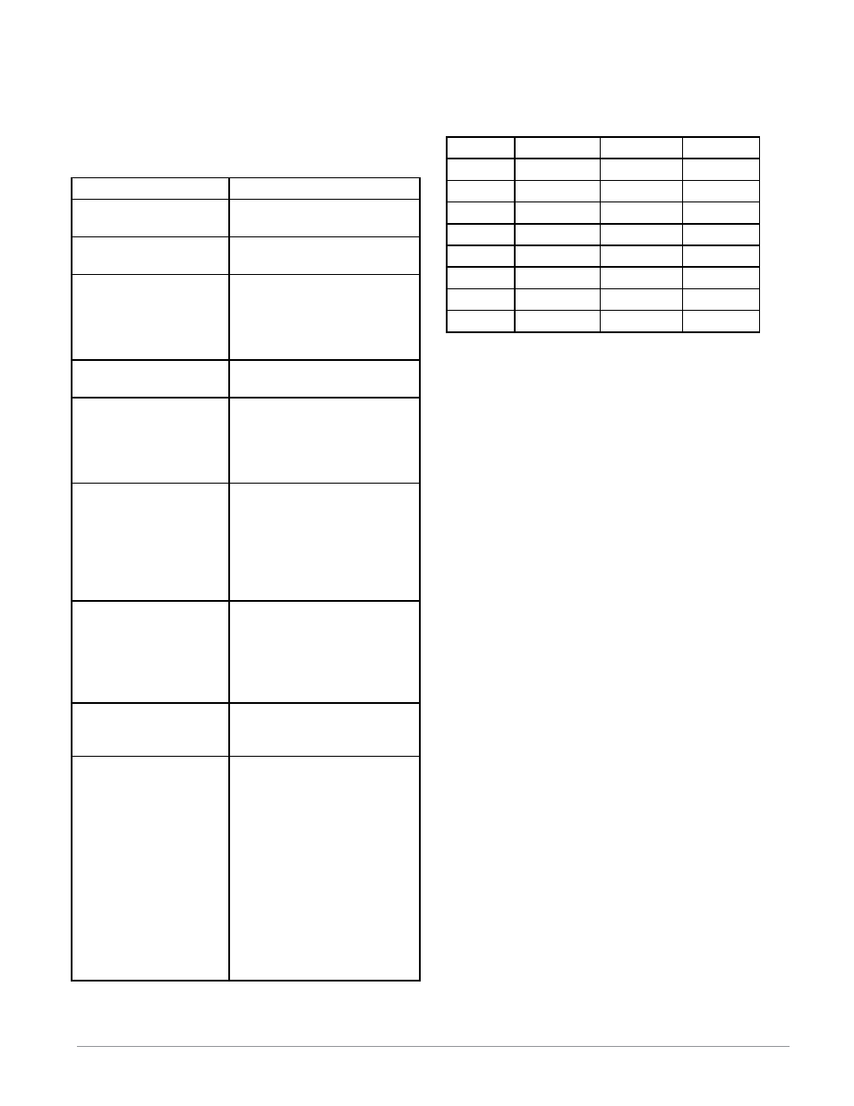
Header Name
Definition
Display
Visually displayed infor-
mation from the control.
Parameter Name
Describes the function of
the given parameter.
Range
Defines options available
for this prompt, i.e., min/
max values (numerical),
yes/no, etc... (further ex-
planation below).
Default
Values as delivered from
the factory.
Modbus Relative Ad-
dress
Identifies unique param-
eters using either the
Modbus RTU or Modbus
TCP protocols (further ex-
planation below).
CIP (Common Indus-
trial Protocol)
If used in conjunction
with an RMA module
identifies unique param-
eters using either the De-
viceNet or EtherNet/IP
protocol (further explana-
tion below).
Profibus Index
If used in conjunction
with an RMA module
identifies unique param-
eters using Profibus DP
protocol (further explana-
tion below).
Parameter ID
Identifies unique param-
eters used with other soft-
ware such as, LabVIEW.
Data Type R/W
uint = Unsigned 16 bit
integer
dint = Signed 32-bit,
long
string = ASCII (8 bits
per character)
float = IEEE 754 32-bit
RWES = Readable
Writable
EEPROM (saved)
User Set (saved)
Display
When the RMA module is used in conjunction with
the RUI (optional equipment) visual information
from the module is displayed to the observer using
a fairly standard 7 segment display. Due to the use
of this technology, several characters displayed need
some interpretation, see the list below:
[1]
= 1
[0]
= 0
[i]
= i
[r]
= r
[2]
= 2
[a ]
= A
[j ]
= J
[s]
= S
[3]
= 3
[ h]
= b
[H]
= K
[ t]
= t
[4]
= 4
[c]
, [C] = c
[L]
= L
[U]
= u
[5]
= 5
[d ]
= d
[ m ]
= M
[u]
= v
[6]
= 6
[ e]
= E
[n]
= n
[ w ]
= W
[7]
= 7
[ f]
= F
[o]
= o
[y ]
= y
[8]
= 8
[g ]
= g
[ p]
= P
[2]
= Z
[9]
= 9
[ h]
= h
[q ]
= q
Range
Within this column notice that on occasion there will
be numbers found within parenthesis. This number
represents the enumerated value for that particular
selection. Range selections can be made simply by
writing the enumerated value of choice using any of
the available communications protocols. As an ex-
ample, turn to the Operations Page and look at the
Backup Menu. To initiate a backup using Modbus
simply right the value of 1644 (save) to Modbus reg-
ister 401271.
Communication Protocols
The RMA module comes with the standard offering
of Watlow's Standard Bus protocol used primarily
for inter-module communications as well as for con-
figuration using EZ-ZONE Configurator software
(free download from Watlow's web site (
http://www.
watlow.com
). Along with Standard Bus, the RMA
module has options for several different protocols
listed below:
- Modbus RTU 232/485
- EtherNet/IP, Modbus TCP
- DeviceNet
- Profibus DP
Modbus RTU Protocol
All Modbus registers are 16-bits and as displayed
in this manual are relative addresses (actual). Some
legacy software packages limit available Modbus
registers to 40001 to 49999 (5 digits). Many applica-
tions today require access to all available Modbus
registers which range from 400001 to 465535 (6 dig-
its). Watlow controls support 6 digit Modbus regis-
ters.
Note:
In this User's Guide, all values shown representing
Modbus addresses are added to 400,001 or 40,001 to
acquire the absolute address. As an example, notice
above (under the Range header) the Modbus address
identified for Backup. Compare this to the value list-
ed for this same parameter found in the Operations