Profibus dp communications, Watlow ez-zone, Rma module – Watlow EZ-ZONE RMA Modul User Manual
Page 19: Chapter 2 install and wire, Rma part # digit 5 and 6 is a6
Watlow EZ-ZONE
®
RMA Module
•
16
•
Chapter 2 Install and Wire
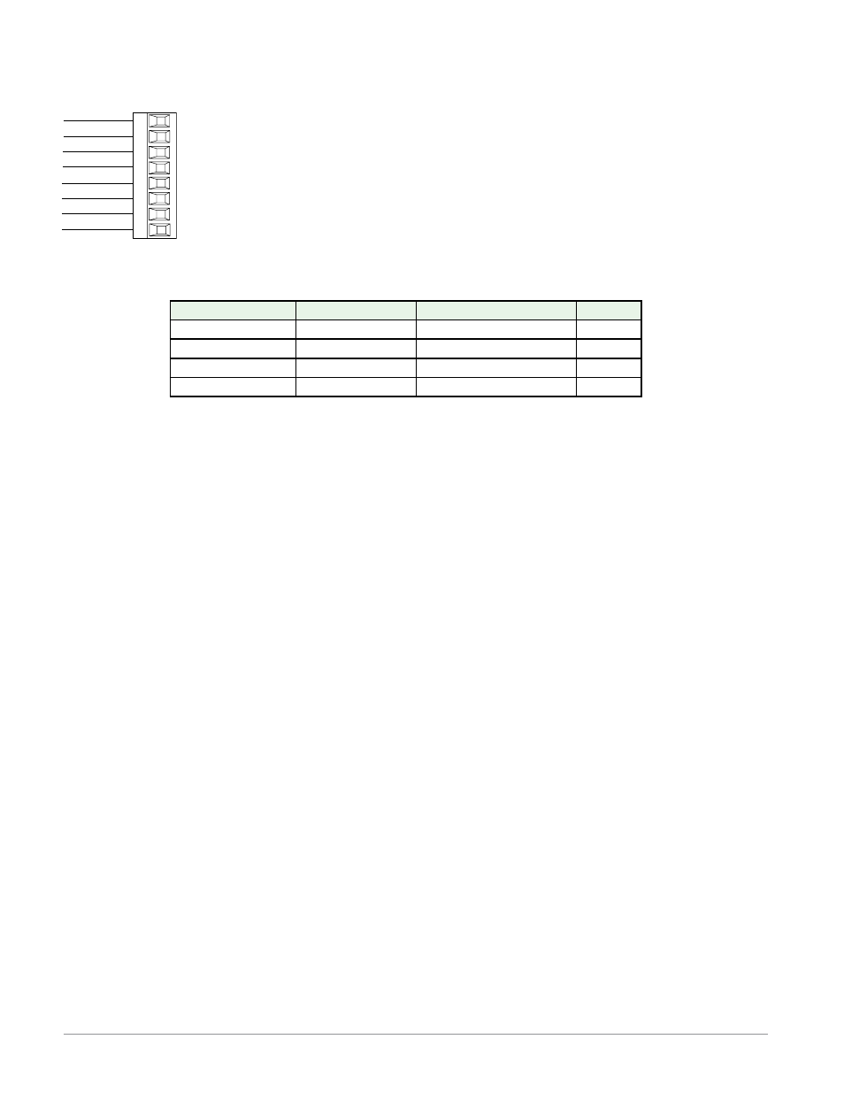
Profibus DP Communications
485 T-/R-
+5Vdc Voltage Potential
VP
B
A
DG
trB
B
A
trA
Slot E
485 T+/R+
Digital ground
Termination resistor B
485 T+/R+
485 T-/R-
Termination resistor A
• Wire T-/R- to the A terminal of the EIA-485 port.
• Wire T+/R+ to the B terminal of the EIA-485
port.
• Wire Digital Ground to the common terminal of
the EIA-485 port.
• Do not route network wires with power wires.
Connect network wires in daisy-chain fashion
when connecting multiple devices in a network.
• A termination resistor should be used if this con-
trol is the last one on the network.
• If using a 150 Ω cable Wat low provides internal
termination. Place a jumper across pins trB and
B and trA and A.
• If external termination is to be used with a 150
Ω cable place a 390 Ω resistor across pins VP
and B, a 220 Ω resistor across pins B and A, and
lastly, place a 390 Ω resistor across pins DG and
A.
• Do not connect more than 16 EZ-ZONE
RM mod-
ules on any given segment.
• Maximum EIA-485 network length: 1,200 meters
(4,000 feet)
• 1/8th unit load on EIA-485 bus.
• Communications instance 2
RMAX - A [6] X X - A A X X
Profibus Terminal
EIA/TIA-485 Name
Watlow Terminal Label
Function
VP (Voltage Potential)
- - - -
VP
+5Vdc
B-Line
B
B
T+/R+
A-Line
A
A
T-/R-
DP-GND
common
DG
common
RMA Part # Digit 5 and 6 is A6