Compact class lsw a, Watlow ez-zone, Rma module – Watlow EZ-ZONE RMA Modul User Manual
Page 71: Chapter 8 appendix
Watlow EZ-ZONE
®
RMA Module
•
68
•
Chapter 8 Appendix
15
14
13
12
11
10
9
8
7
6
5
4
3
2
1
0
Input
error
status
Loop
error
status
Tune
status
15
14
13
12
11
10
9
8
7
6
5
4
3
2
1
0
Input
error
status
15
14
13
12
11
10
9
8
7
6
5
4
3
2
1
0
15
14
13
12
11
10
9
8
7
6
5
4
3
2
1
0
Spare
Input
error
status
Spare
Input
error
status
Spare
Input
error
status
Spare
Input
error
status
Spare
Input
error
status
Spare
Input
error
status
Spare
Input
error
status
Spare
Input
error
status
15
14
13
12
11
10
9
8
7
6
5
4
3
2
1
0
Input
error
status
15
14
13
12
11
10
9
8
7
6
5
4
3
2
1
0
15
14
13
12
11
10
9
8
7
6
5
4
3
2
1
0
15
14
13
12
11
10
9
8
7
6
5
4
3
2
1
0
spare
Open
loop
clear
Initiate
tune
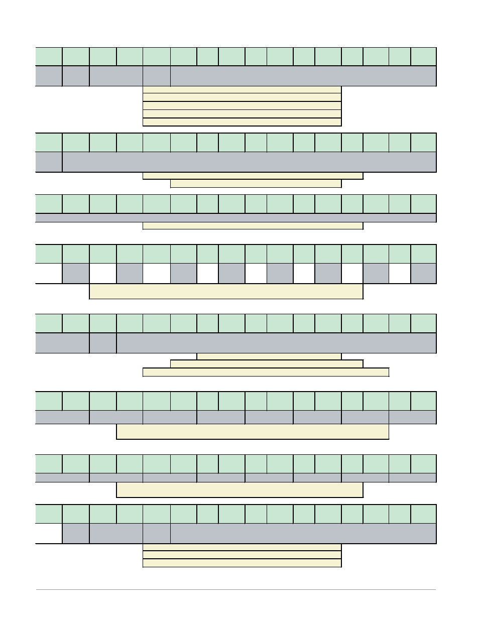
Bits 0 to 15, This member has paired bits which represent the state of up to 16 alarms (00 = None, 01
= Alarm Low, 10 = Alarm High, 11 = Other)
Bits 14 to 15, Limit State (00 = None, 01 = Limit Low, 10 = Limit High, 11 = Other)
Bits 0 to 12, Signed 13 bits, whole (-4096 to 4095)
Bits 13 and 29, Analog Input Error Status (0 = None, 1 = Error)
Bits 0, 2, 4, 6, 8, 10, 12 and 14, Re flect the Analog Input Error Status for instance i to
instance i + 15 respectively (0 = None, 1 = Error)
Limit state
Limit state
Limit state
Limit state
Limit state
Alarm state
Bits 0 to 15, This member has paired bits which represent the state of up to 16 limit (00 = None, 01 = Limit Low,
10 = Limit High,
Limit state
Alarm state
Alarm state
Alarm state
Alarm state
Control
Mode
Open Loop Set Point (instance i)
Filtered Analog Input Value (instance i)
Filtered Analog Input Value (instance i)
Alarm state
Alarm state
Bits 0 to 14, Signed 15 bits with implied tenths precision (-1638.4 to 1638.3)
Control Loop Output Power (instance i)
Actual CM
Bits 0 to 10, Signed 10 bits with implied tenths precision (-100.0 to 100.0)
Bit 11, Loop Tuning Status (0 = Off, 1 = Error)
Limit state
Analog Input Value (instance i)
Bits 12 and 13, Actual Control Mode (00 = Off, 01 = Manual, 10 = Auto)
Bit 15, Analog Input Error Status (0 = None, 1 = Error)
Bit 14, Loop Error Status (0 = None, 1 = Error)
Bit 15, Analog Input Error Status (0 = None, 1 = Error)
Bits 0 to 15, Signed 16 bits with implied tenths precision (-3276.8 to 3276.7)
Bits 0 to 10, Signed 10 bits with implied tenths precision (-100.0 to 100.0)
Bit 12 and 13, Control Mode (00 = Off, 01 = Manual, 10 = Auto)
Bit 14, Clear an Open loop Condition (0 = Ignore, 1 = Clear)
Alarm state
Limit state
Limit state
Compact Class LSW A