Compact class msw a, Watlow ez-zone, Rma module – Watlow EZ-ZONE RMA Modul User Manual
Page 70: Chapter 8 appendix
Watlow EZ-ZONE
®
RMA Module
•
67
•
Chapter 8 Appendix
Assembly
Class,
Instance,
Attribute
Module
Availabilty
31
30
29
28
27
26
25
24
23
22
21
20
19
18
17
16
Control Loop
T2O
RMH
Assembly
Class,
Instance,
Attribute
Module
Availabilty
31
30
29
28
27
26
25
24
23
22
21
20
19
18
17
16
Analog Input
T2O
Input
error
status
Assembly
Class,
Instance,
Attribute
Module
Availabilty
31
30
29
28
27
26
25
24
23
22
21
20
19
18
17
16
Assembly
Class,
Instance,
Attribute
Module
Availabilty
31
30
29
28
27
26
25
24
23
22
21
20
19
18
17
16
Analog Input
T2O
(C) 0x71 (113)
(I) 1 to 24
(A) 0x11 (17)
RMH
RML
RMS
Spare
Input
error
status
Spare
Input
error
status
Spare
Input
error
status
Spare
Input
error
status
Spare
Input
error
status
Spare
Input
error
status
Spare
Input
error
status
Spare
Input
error
status
Assembly
Class,
Instance,
Attribute
Module
Availabilty
31
30
29
28
27
26
25
24
23
22
21
20
19
18
17
16
Limit Loop
T2O
(C) 0x71 (113)
(I) 1 to 24
(A) 6
RML
Input
error
status
Assembly
Class,
Instance,
Attribute
Module
Availabilty
31
30
29
28
27
26
25
24
23
22
21
20
19
18
17
16
RML
Assembly
Class,
Instance,
Attribute
Module
Availabilty
31
30
29
28
27
26
25
24
23
22
21
20
19
18
17
16
Assembly
Class,
Instance,
Attribute
Module
Availabilty
31
30
29
28
27
26
25
24
23
22
21
20
19
18
17
16
Control Loop
O2T
(C) 0x71 (113)
(I) 1 to 24
(A) 2
RMH
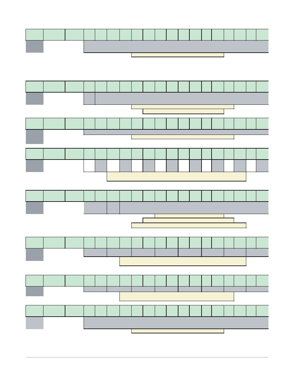
Bits 16 to 31, This member has paired bits which represent the state of up to 16 alarms (00 = None, 01
= Alarm Low, 10 = Alarm High, 11 = Other)
Bits 16 to 28, Signed 13 bits, whole (-4096 to 4095)
Bit 29, Analog Input Error Status (0 = None, 1 = Error)
Bits 30 to 31, Limit State (00 = None, 01 = Limit Low, 10 = Limit High, 11 = Other)
Bits 16, 18, 20, 22, 24, 26, 28 and 30, Reflect the Analog Input Error Status for instance i to
instance i + 15 respectively (0 = None, 1 = Error)
Limit state
Limit state
Bits 16 to 31, This member has paired bits which represent the state of up to 16 limit (00 = None, 01 = Limit Low,
10 = Limit High,
Limit state
Alarm state
Alarm state
Alarm state
Limit state
Analog Input Value (instance i + 1)
Limit state
Closed Loop Set Point (instance i)
Analog Input
T2O
(C) 0x71 (113)
(I) 1 to 24
(A) 9
(C) 0x71 (113)
(I) 1 to 24
(A) 0x0C (12)
Limit Loop
T2O
(C) 0x71 (113)
(I) 1 to 24
(A) 0x0F (15)
(C) 0x71 (113)
(I) 1 to 24
(A) 0x10 (16)
Filtered Analog Input Value (instance i + 1)
Limit
state
Limit state
RMH
RML
RMS
RMH
RML
RMS
Bit 31, Analog Input Error Status (0 = None, 1 = Error)
(C) 0x71 (113)
(I) 1 to 24
(A) 1
Filtered Analog Input Value (instance i)
Bits 16 to 31, Signed 16 bits with implied tenths precision (-3276.8 to 3276.7)
Alarm state
Alarm state
Limit state
Alarm T2O
Alarm state
Alarm state
RMH
RML
RMS
Alarm state
Bits 16 to 30, Signed 15 bits with implied tenths precision (-1638.4 to 1638.3)
Bit16 to 31, Signed 16 bits with implied tenths precision (-3276.8 to 3276.7)
Filtered Analog Input Value (instance i + 1)
Bits 16 to 31, Signed 16 bits with implied tenths precision (-3276.8 to 3276.7)
Limit state
Compact Class MSW A