Standard bus eia-485 communications, Low power, Watlow ez-zone – Watlow EZ-ZONE RMA Modul User Manual
Page 17: Rma module, Chapter 2 install and wire
Warning:
ç
Use National Electric (NEC) or other
country-specific standard wiring and
safety practices when wiring and
connecting this controller to a power
source and to electrical sensors or pe-
ripheral devices . Failure to do so may
result in damage to equipment and
property, and/or injury or loss of life .
Note:
Maximum wire size termination and
torque rating:
• 0 .0507 to 3 .30 mm2 (30 to 12 AWG)
single-wire termination or two 1 .31
mm2 (16 AWG)
• 0 .8 Nm (7 .0 in-lb .) torque
Note:
Adjacent terminals may be labeled
differently, depending on the model
number .
Note:
To prevent damage to the controller,
do not connect wires to unused ter-
minals .
Note:
Maintain electrical isolation between
digital input-outputs, switched dc/open
collector outputs and process outputs
to prevent ground loops .
Note:
This Equipment is suitable for use in
CLASS I, DIVISION 2, Groups A, B,
C and D or Non-Hazardous locations
only . Temperature Code T4
Warning:
ç
Explosion Hazard – Substitution of
component may impair suitability for
CLASS I, DIVISION 2 .
Warning:
ç
Explosion Hazard - Do not disconnect
while the circuit is live or unless the
area is known to be free of ignitable
concentrations of flammable sub-
stances .
Watlow EZ-ZONE
®
RMA Module
•
14
•
Chapter 2 Install and Wire
Access Module Wiring (RMAx-xxxx-xxxx)
• CF, CD, CE - Standard Bus EIA485 Communications
• CZ, CX, CY - Inter-module Bus EIA485 Communications
• Do not route network wires with power wires. Connect net-
work wires in daisy-chain fashion when connecting multiple
devices in a network
• Wire T-/R- to the A terminal of the EIA-485 port.
• Wire T+/R+ to the B terminal of the EIA-485 port.
• Wire common to the common terminal of the EIA-485 port.
• Do not route network wires with power wires. Connect net-
work wires in daisy-chain fashion when connecting multiple
devices in a network.
• A 120 Ω termination resistor may be required across T+/R+
and T-/R-, placed on the last controller on the network.
• Do not connect more than 16 EZ-ZONE RM controllers on a
network.
• Maximum network length: 1,200 meters (4,000 feet)
• 1/8th unit load on EIA-485 bus
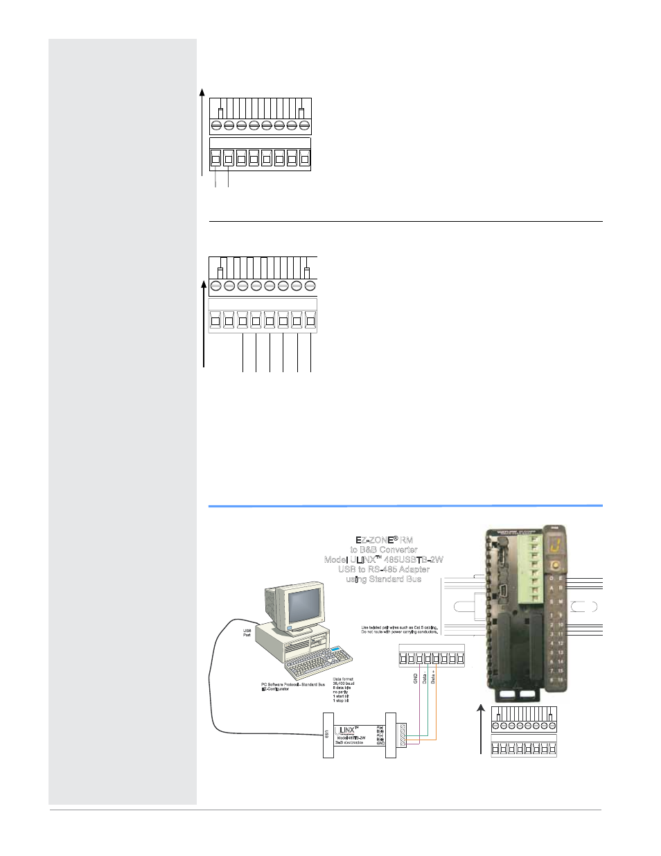
Standard Bus EIA-485 Communications
Standar
d Bus
Common
T- / R-
Int
er
-module Bus
Common
- +
T+ / R+
CF
CY
CX
CZ
CE
CD
Slot C
Low Power
• 20.4 to 30.8 V Å (ac) / Î (dc)
• 47 to 63 Hz
• Access module power consumption, 4 Watts maximum
• 31 Watts maximum power available for P/S part #:0847-0299-
0000
• 60 Watts maximum power available for P/S part #:0847-0300-
0000
• 91 Watts maximum power available for P/S part #:0847-0301-
0000
• Class 2 or SELV power source required to meet UL compliance
standards
po
w
er
98 99
Slot C
Slot C
98 99 CF CD CE CZ CW CY
98 99 CF CD CE CZ CW CY
Use twisted pair wires such as Cat 5 cabling.
Do not route with power carrying conductors.
LINX
Model 485TB-2W
U
S
B
A(-)
A(-)
B(+)
B(+)
GND
B B electronics
&
TM
U
USB Serial Conversion
0847-0326-0000
EZ-ZONE
®
RM
to B&B Converter
Model ULINX 485USBTB-2W
USB to RS-485 Adapter
using Standard Bus
TM
USB
Port
Data format
38,400 baud
8 data bits
no parity
1 start bit
1 stop bit
PC Software Protocol - Standard Bus
EZ-Configurator