Devicenet™ communications, Ethernet/ip™ and modbus tcp communications – Watlow EZ-ZONE RMA Modul User Manual
Page 18
Watlow EZ-ZONE
®
RMA Module
•
15
•
Chapter 2 Install and Wire
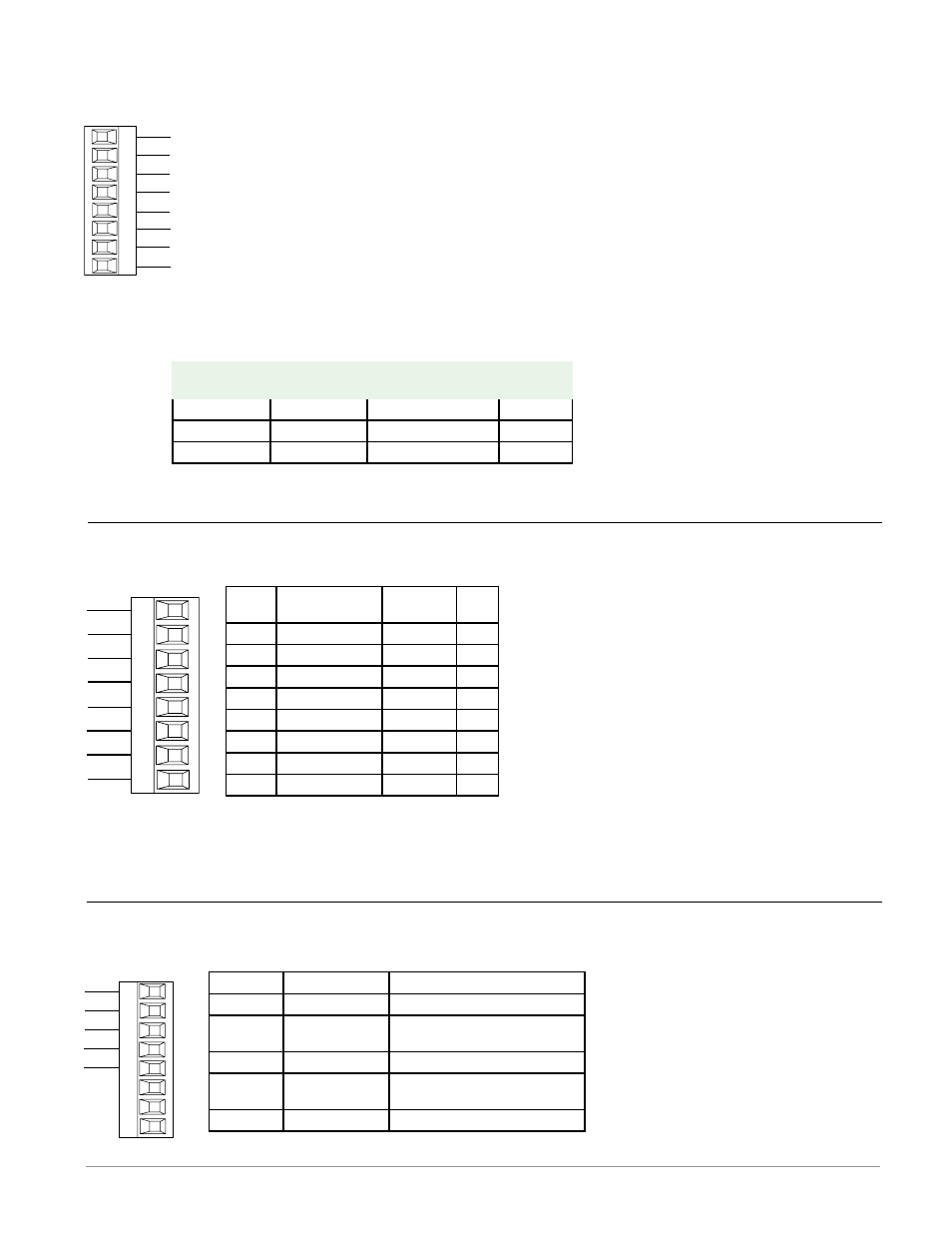
Terminal
Signal
Function
V+
V+
DeviceNet™ power
CH
CAN_H
positive side of DeviceNet™
bus
SH
shield
shield interconnect
CL
CAN_L
negative side of DeviceNet™
bus
V-
V-
DeviceNet™ power return
DeviceNet™ Communications
CAN_L
V-
V+
CH
SH
CL
V-
T2
S2
R2
Slot E
V+
CAN_H
shield
RMA Part # Digit 5 and 6 is A5
receive -
unused
E8
E7
E6
E5
E4
E3
E2
E1
Slot E
unused
unused
unused
receive +
transmit -
transmit +
RJ-45
pin
T568B wire
color
Signal
Slot
E
8
brown
unused
E8
7
brown & white
unused
E7
6
green
receive -
E6
5
white & blue
unused
E5
4
blue
unused
E4
3
white & green
receive +
E3
2
orange
transmit -
E2
1
white & orange
transmit + E1
EtherNet/IP™ and Modbus TCP communica-
tions to connect with a 10/100 switch .
• Do not route network wires with power
wires.
• Connect one Ethernet cable per controller
to a 10/100 mbps Ethernet switch. Both
Modbus TCP and EtherNet/IP™ are avail-
able on the network.
EtherNet/IP™ and Modbus TCP Communications
RMA Part # Digit 5 and 6 is A3
Modbus-IDA
Terminal
EIA/TIA-485
Name
Watlow Terminal
Label
Function
DO
A
CA or CD
T-/R-
D1
B
CB or CE
T+/R+
common
common
CC or CF
common
T-/R-
common
CB
CA
CC
CB
CA
C5
C3
C2
Slot E
T+/R+
232 (RD) to DB9 pin 3 (Tx)
T-/R-
T+/R+
232 (Tx) to DB9 pin 2 (RD)
232 common
• Wire T-/R- to the A terminal of
the EIA-485 port.
• Wire T+/R+ to the B terminal of
the EIA-485 port.
• Wire common to the common
terminal of the EIA-485 port.
• Do not route network wires
with power wires. Connect net-
work wires in daisy-chain fash-
ion when connecting multiple
devices in a network.
• A termination resistor is re-
quired. Place a 120 Ω resistor
across T+/R+ and T-/R- of last
controller on network.
• Maximum number of devices on
a Modbus network is 247.
• maximum network length:
1,200 meters (4,000 feet)
• maximum EIA-232 network
length: 15 meters (50 feet)
• Do not connect more than one
EZ-ZONE RM controller on an
EIA-232 network.
• Do not wire to both the EIA-485
and the EIA-232 pins at the
same time.
• Two EIA-485 terminals of T/R
are provided to assist in daisy-
chain wiring.
• 1/8th unit load on EIA-485 bus.
EIA-232/485 Modbus RTU Communications
RMA Part # Digit 5 and 6 is A2
Notes:
When using EtherNet/IP the RMA module supports implicit and unconnected explicit messaging.