Watlow EZ-ZONE RMA Modul User Manual
Page 8
Watlow EZ-ZONE
®
RMA Module
•
5
•
Chapter 1 Overview
Module Orientation
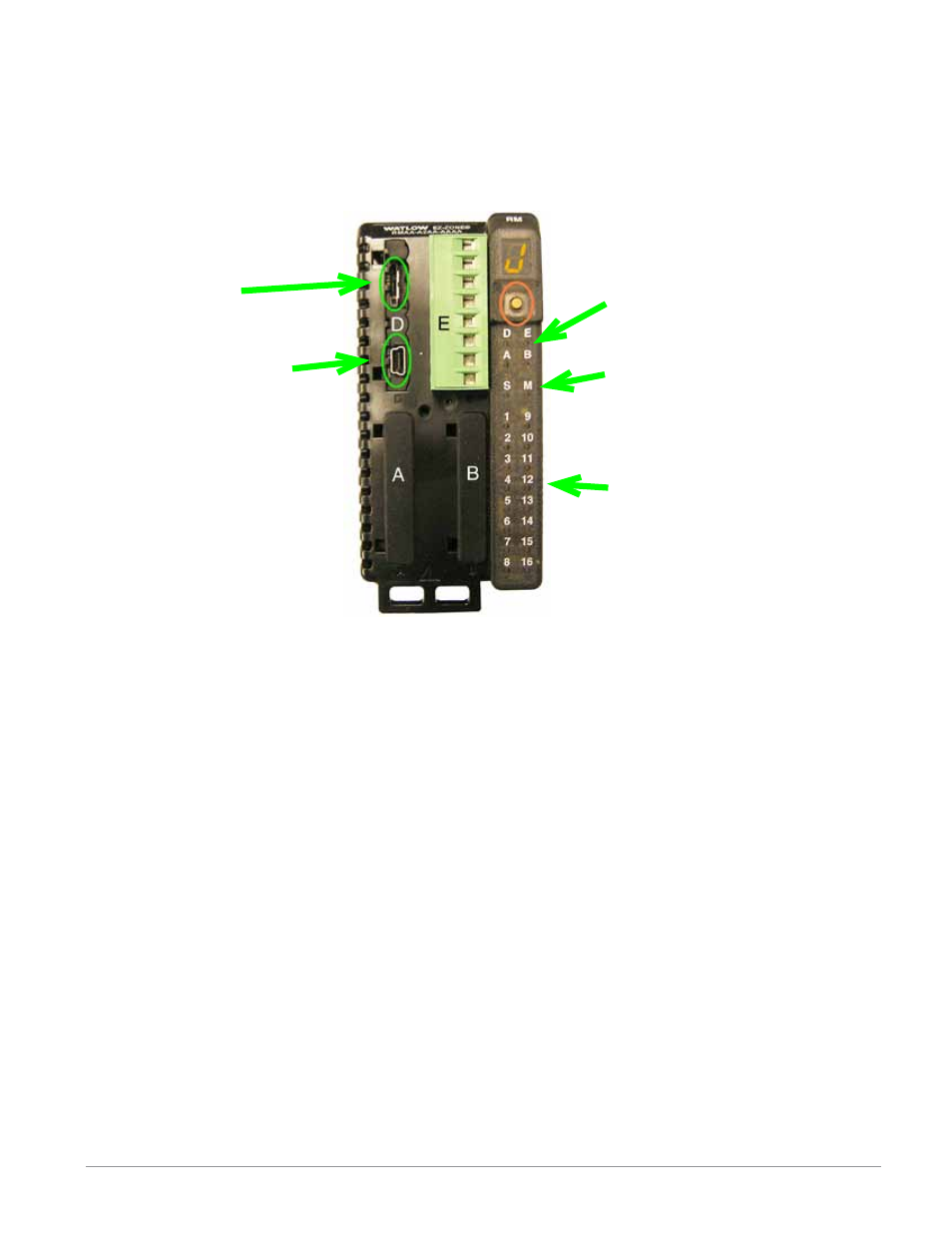
The picture below reflects a front view of an RMA module. Like all RM modules, there are four slots that
appear on the face (slot A, B, D, and E) of the module and one on the bottom (slot C) not shown. For this
particular module only slots D and E can be used. On the face of the module there is a button (orange circle)
under the Zone address [J] that when pushed and held has the following function:
1.Push and hold for ~ 2 seconds to change the Zone address. Valid addresses range from 1 -17 ([1] - [9], [a] is
10, [b] is 11, [C] is 12, [d] is 13, [e] is 14, [f] is 15, and [h] is 16). The Access module is shipped (default fac-
tory address) at address [j] or 17
SD Card
USB, Mini Type B
connector
Module Status (Slot A, B, D,
or E not used on this module)
Backplane Protocol (For this
module always set to Stan-
dard Bus -red)
Output indicators (1 to 16)
not used on this module.
- 12LS Controller (111 pages)
- 8LS Controller (140 pages)
- 8PID Controller (55 pages)
- Addendum to EZwarePlus (50 pages)
- ANASCAN (62 pages)
- ANASOFT (95 pages)
- ANAWIN 2 (154 pages)
- ANAWIN 3 (23 pages)
- Calibrating Watlow Series 988 Family Process Controls (19 pages)
- CAS (98 pages)
- CAS200 (124 pages)
- CLS (180 pages)
- CLS200 (251 pages)
- CLS200, MLS300 and CAS200 (92 pages)
- Control Console (12 pages)
- CPC400 (230 pages)
- DIN-A-MITE Style A (9 pages)
- DIN-A-MITE Style B (14 pages)
- DIN-A-MITE Style C (22 pages)
- DIN-A-MITE Style D (9 pages)
- DIN-Mount Adapter Instruction Sheet, Rev A (1 page)
- Dual DAC (4 pages)
- EM Gateway (28 pages)
- E-Safe Hybrid Relay Rev B (4 pages)
- E-SAFE II Hybrid Power Switch (4 pages)
- EZwarePlus Programming (264 pages)
- EZ-ZONE PM (111 pages)
- EZ-ZONE PM PID (125 pages)
- EZ-ZONE PM Express Limit (34 pages)
- EZ-ZONE PM Express (35 pages)
- EZ-ZONE PM Integrated Controller (181 pages)
- EZ-ZONE RM Limit Module Rev C (127 pages)
- EZ-ZONE RMC (236 pages)
- EZ-ZONE RME (124 pages)
- EZ-ZONE RMH (161 pages)
- EZ-ZONE RUI/Gateway (62 pages)
- EZ-ZONE RM-Scanner-Modul (140 pages)
- EZ-ZONE ST (97 pages)
- F4 External Event Board - Rev.B (2 pages)
- HG Series Mercury Displacement Relay (6 pages)
- LogicPro (296 pages)
- Mercury Relay or MDR Retrofit (13 pages)
- MICRODIN (24 pages)
- MICRODIN (106 pages)