Instruction 109- decode – Maple Systems MAPware-7000 User Manual
Page 182
MAPware-7000 Ladder Logic Guide
174
1010-1041 rev. 00
Instruction 109-
Decode
Expression:
Space Requirement: 1 line x 5 column Location Requirement: Middle, Right rail
Function:
When the input is ON, this instruction sets the bit, which is designated by the lower n bits of A,
to ON in the bit table of size 2
n
bits starting with 0 bit (LSB) of B, and resets all other bits to OFF.
Execution Condition:
Input
Operation
Output
OFF
No execution
OFF
ON
Execution
ON
Operand:
Coil or Bit
Register
Constant
Index
Name
X
Y B
S
T.
C.
M
X
W
Y
W
B
W
S
W
T C
D
I
J
K
M
W
A
Decode
Source
√
√
√
√
√ √
√
√
√
√
N
Table Size
1-8
B
Start of
Table
√
√
√
√ √
√
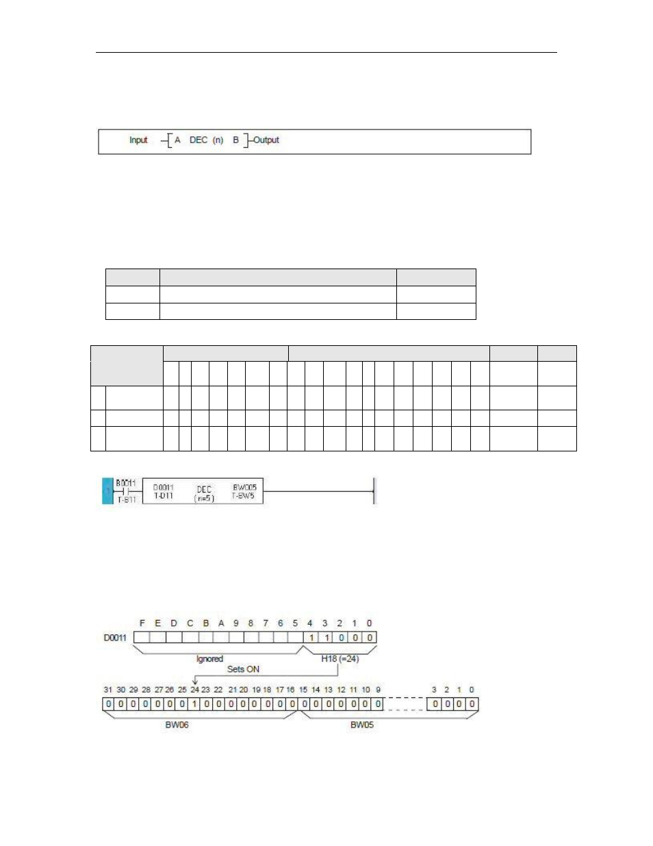
Example:
2
5
(=32) bits starting with 0 bit of BW05 (B080 to B111) are defined as the bit table.
When B011 is ON, the bit position designated by lower 5 bits of D0011 in the bit table is
set to ON, and all other bits in the table are reset to OFF.
The following figure shows an operation example.