Instruction 61- bi-directional shift register – Maple Systems MAPware-7000 User Manual
Page 107
99
MAPware-7000 Ladder Logic Guide
1010-1041 rev. 00
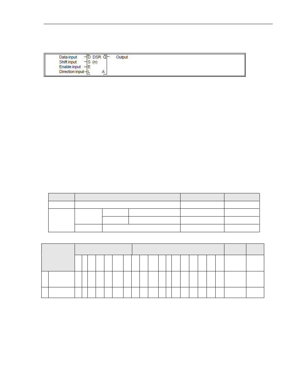
Instruction 61-
Bi-directional
Shift Register
Expression:
Space Requirement: 4 line x 3 column Location Requirement: Middle, Right rail
Function:
While the enable input (E) is ON, this instruction shifts the data of the bit table, size n starting
with A, 1 bit when the shift input (S) is ON. The shift direction is determined by the state of the
direction input (L).
When L is OFF, the direction is right (lower address direction).
When L is ON, the direction is left (upper address direction).
The state of the data input (D) is stored in the highest bit if right shift, and stored in the lowest
bit A if left shift. The pushed out bit state is stored in the carry flag (CF = S976).
When the enable input (E) is OFF, all bits in the table and the carry flag are reset to O.
Execution Condition:
Input
Operation
Output
CF
OFF
Reset all bits in the bit table
OFF
Reset
ON
S = ON
L = ON
Shift left execution
Highest bit state
Set or Reset
L = OFF
Shift right execution
Lowest bit state
Set or Reset
S = OFF
No execution
Highest bit state
---
Operand:
Coil or Bit
Register
Constant
Index
Name
X
Y B
S
T.
C.
M
X
W
Y
W
B
W
S
W
T C
D
I
J
K
M
W
A
Leading
Device
√ √
√
n
Device Size
1-64