Instruction 60- shift register – Maple Systems MAPware-7000 User Manual
Page 105
97
MAPware-7000 Ladder Logic Guide
1010-1041 rev. 00
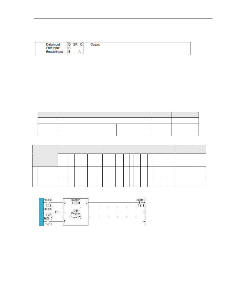
Instruction 60- Shift Register
Expression:
Space Requirement: 3 line x 3 column Location Requirement: Middle, Right rail
Function:
While the enable input is ON, this instruction shifts the data of the bit table, size n starting with
A, 1 bit to the left (upper address direction) when the shift input is ON. The state of the data
input is stored in A. The pushed out bit state is stored in the carry flag (CF = S976).
When the enable input is OFF, all bits in the table and the carry flag are reset to OFF.
Execution Condition:
Input
Operation
Output
CF
OFF
Reset all bits in the bit table
OFF
Reset
ON
When the shift input is ON
Shift execution
ON
Set or Reset
When the shift input is OFF
No execution
OFF
---
Operand:
Coil or Bit
Register
Constant
Index
Name
X
Y B
S
T.
C.
M
X
W
Y
W
B
W
S
W
T C
D
I
J
K
M
W
A
Leading
Device
√ √
√
n
Device Size
1-64
Example:
32 devices starting with B100 (B100 to B131) is specified as a shift register.
When B010 is OFF, the data of the shift register is reset to 0. (B100 to B131 are reset to OFF).
The carry flag (CF = S976) is also reset to OFF.