Instruction 71- 7 segment decode – Maple Systems MAPware-7000 User Manual
Page 120
MAPware-7000 Ladder Logic Guide
112
1010-1041 rev. 00
Instruction 71- 7 Segment Decode
Expression:
Space Requirement: 1 line x 5 column Location Requirement: Middle, Right rail
Function:
When the input is ON, this instruction converts the lower 4 bits data of A into the 7 segment
code, and stores it in B. The 7 segment code is normally used for a numeric display LED.
Execution Condition:
Input
Operation
Output
OFF
No execution
OFF
ON
Execution
ON
Operand:
Coil or Bit
Register
Constant
Index
Name
X
Y B
S
T.
C.
M
X
W
Y
W
B
W
S
W
T C
D
I
J
K
M
W
A
Source
√
√
√
√
√ √
√
√
√
√
√
B
Destination
√
√
√
√ √
√
√
√
√
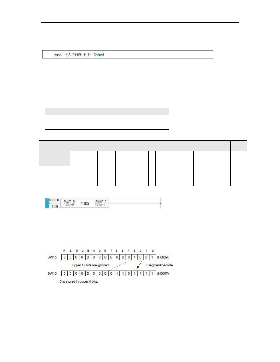
Example:
When X000 is ON, the lower 4 bits data of BW15 is converted into the 7 segment code, and the
result is stored in lower 8 bits of BW10. 0 is stored in upper 8 bits of BW10.
For example, if BW15 is H0009, the corresponding 7 segment code H006F is stored in BW1.
The 7 segment code conversion table is shown on the next page.