Maple Systems MAPware-7000 User Manual
Page 15
7
MAPware-7000 Ladder Logic Guide
1010-1041 rev. 00
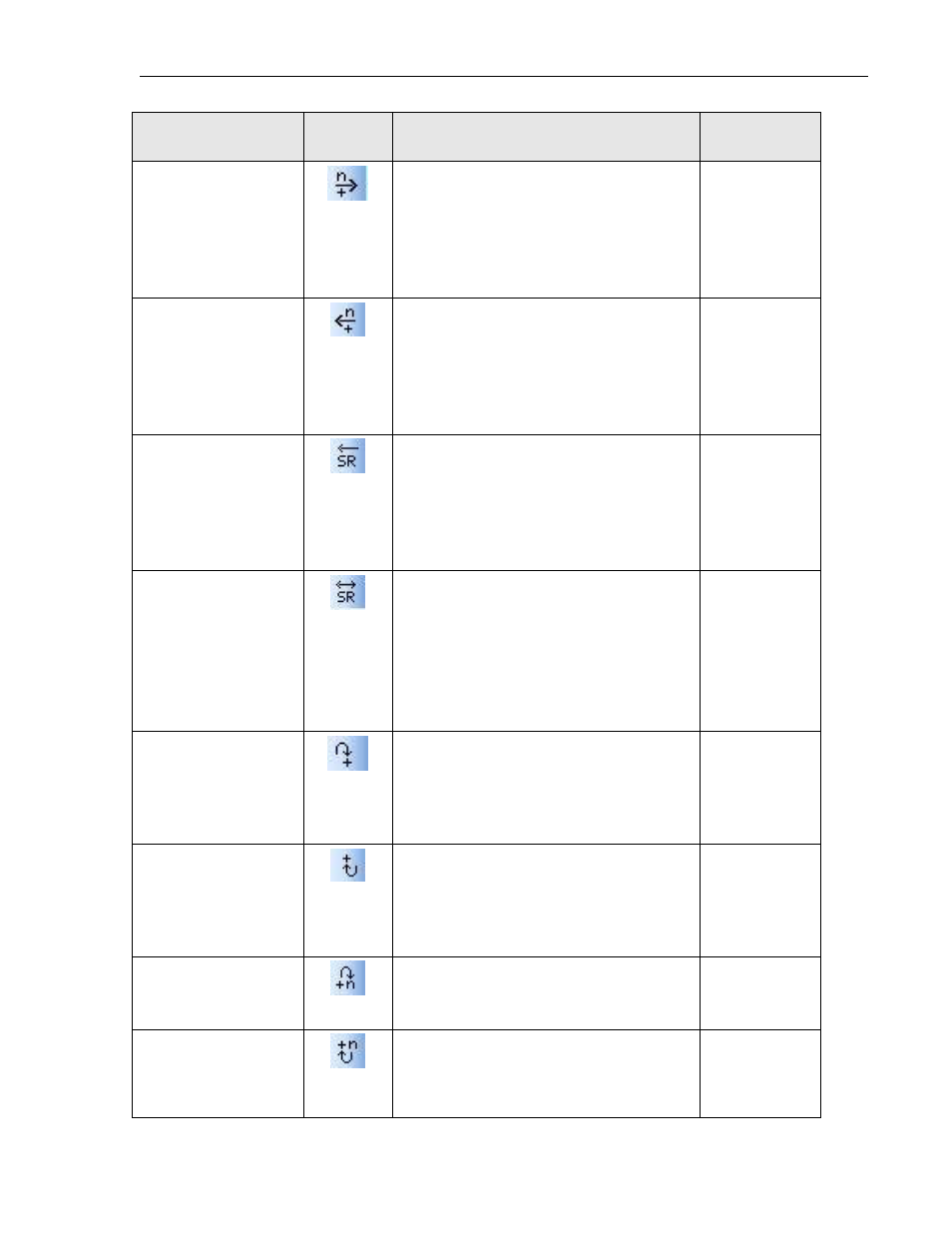
Instruction Name
Symbol
Description
Execution
Time (μSec)
N bits shift right
The data in Operand A is shifted n bits (1-
16) to the right (LSB direction) and stored
in Operand B and the carry bit. Note: the
carry bit (S0) is the location of the 1
st
rightmost bit after the shift.
2.5 μsec
N bits shift left
The data in Operand A is shifted n bits (1-
16) to the left (MSB direction) and stored
in Operand B and the carry bit. Note: the
carry bit (S0) is the location of the 1
st
leftmost bit after the shift.
2.5 μsec
Shift Register
While the enable input is ON, this
instruction shifts the data of the bit table,
size n (1 to 64) starting with A, 1 bit to
the left (upper address direction) when
the shift input is ON.
15.5 μsec to
36.6 μsec
Bi-directional shift
register
While the enable input (E) is ON, this
instruction shifts the data of the bit table,
size n (1 to 64) starting with A, 1 bit when
the shift input (S) is ON. The shift
direction is determined by the state of
the direction input (L).
21.7 μsec to
42.2 μsec
1 bit rotate right
The data in the selected register is shifted
1 bit to the right (LSB direction). The least
significant bit is moved to the most
significant bit.
2.1 μsec
1 bit rotate left
The data in the selected register is shifted
1 bit to the left (MSB direction). The most
significant bit is moved to the least
significant bit.
2.1 μsec
N bits rotate right
The data in Operand A is shifted n bits
(1
to 16)
to the right (LSB direction) and
stored in Operand B.
2.4 μsec
N bits rotate left
The data in Operand A is shifted n bits
(1
to 16)
to the left (MSB direction) and
stored in Operand B.
2.4 μsec