Maple Systems HMC7000 Series User Manual
Page 77
HMC7000 Series I/O Module Guide
Phone: 425/745-3229 • Fax: 425/745-3429 • Email: [email protected] • www.maplesystems.com
.
1010-1043
Page 76 of 85
Rev. 02, 11/08/2013
Configuration of the HMC7000 Series High Speed Counters
Maple Systems’ HMC products have built-in High-Speed counters that link directly to specific inputs and
outputs. Specific registers and bits are predefined for setup and control of these counters. No logic is
required to run the counters, other than logic that may be used to configure and control the counters.
Two inputs on the module are used as the Triggers for the High-Speed counters, and two outputs are used
as the Done bits. The inputs support a maximum speed of 25 KHz.
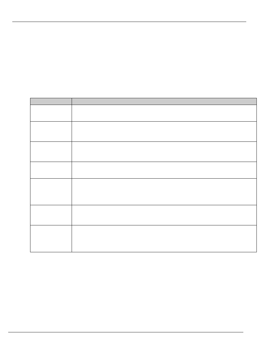
The following bits and registers are associated with a High-Speed counter:
Register/ Bit
Description
Configuration
Register
The 16-bit register that controls how the High-Speed counter operates.
Bits 3-0 are used (see below)
Current Count
Register
The 32-bit register that counts the number of times that the Trigger has transitioned. The
specified register is the Least Significant Word (LSW); the next consecutive register is
the Most Significant Word (MSW).
Preset Register
The 32-bit register that defines the number of counts at which the Done bit will be set
(see description of Done Bit below). The specified register is the Least Significant Word
(LSW); the next consecutive register is the Most Significant Word (MSW).
Trigger Bit
The input bit that triggers the count. The counter will increment by one on each bit
transition. The counter can operate on a falling (default) or rising edge.
Enable Bit
The counter will not run unless this bit is set. If this bit is reset while the counter is
running, the current values will be maintained, but the Trigger bit will have no effect.
The Done bit is reset if the Enable bit is reset. If the Current Count value is greater than
or equal to the Preset value, the Done bit is set after the Enable bit is set again.
Reset Bit
When this bit goes from false to true, the current count will reset to 0 and the Done bit is
reset. The reset occurs even when the Enable bit is reset. The reset is accomplished by
an internal bit or a physical input.
Done Bit
The physical output that turns on when the Current Count is equal to or greater than the
Preset value. The bit remains set until the Reset bit goes true, even if the counter counts
beyond the preset. If the Enable bit is reset, the Done bit will reset. If the Enable bit is
set while the Current Count is equal to or greater than the Preset, the Done bit is set.