Maple Systems HMC7000 Series User Manual
Page 22
HMC7000 Series I/O Module Guide
Phone: 425/745-3229 • Fax: 425/745-3429 • Email: [email protected] • www.maplesystems.com
.
1010-1043
Page 21 of 85
Rev. 02, 11/08/2013
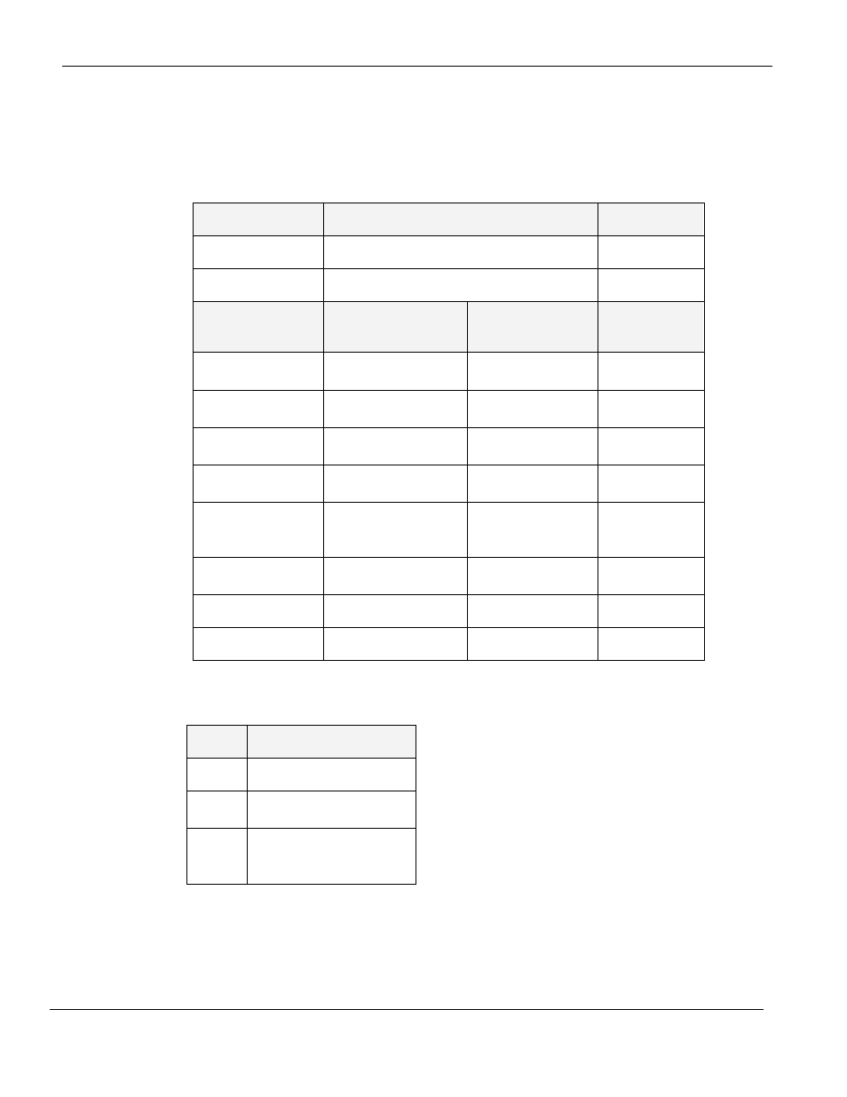
Configuration:
Use MAPware-7000 to assign input (X and XW), output (Y and YW), and configuration (M and MW)
memory addresses to the module. These addresses are created according to the slot location of the module,
where nn refers to the slot number
(ex. 01…05):
Function
Register
Access
X0-X7 Inputs
Xnn000-007 (XWnn00)
Rd Only
Y0-Y7 Outputs
Ynn000-007 (YWnn00)
Rd/Write
High Speed
Counter Option
HSC Channel 1
HSC Channel 2
HSC Input
X0 (terminal)
Xnn000 (reg)
X5 (terminal)
Xnn005 (reg)
Rd Only
HSC Reset Input
X1 (terminal)
Xnn001 (reg)
X6 (terminal)
Xnn006 (reg)
Rd Only
HSC Output Flag
Y1 (terminal)
Ynn001 (reg)
Y6 (terminal)
Ynn006 (reg)
Rd/Write
HSC Configuration
Register
MWnn00
MWnn06
Rd/Write
HSC Counter
Register
(Current Value)
MWnn01
MWnn02
MWnn07
MWnn08
Rd/Write
HSC Preset Register
MWnn03
MWnn04
MWnn09
MWnn10
Rd/Write
HSC Enable Bit
Mnn080
Mnn176
Rd/Write
HSC Reset Bit
Mnn081
Mnn177
Rd/Write
Reference the table below when configuring each HSC Configuration Register (MWnn00 and MWnn06):
Bits
Function
15-4
Not used
3
0 : Falling Edge
1 : Rising Edge
2, 1, 0
Module Operating Mode :
000 : Normal Operation
010 : Up Counter HSC