Maple Systems HMC7000 Series User Manual
Page 70
HMC7000 Series I/O Module Guide
Phone: 425/745-3229 • Fax: 425/745-3429 • Email: [email protected] • www.maplesystems.com
.
1010-1043
Page 69 of 85
Rev. 02, 11/08/2013
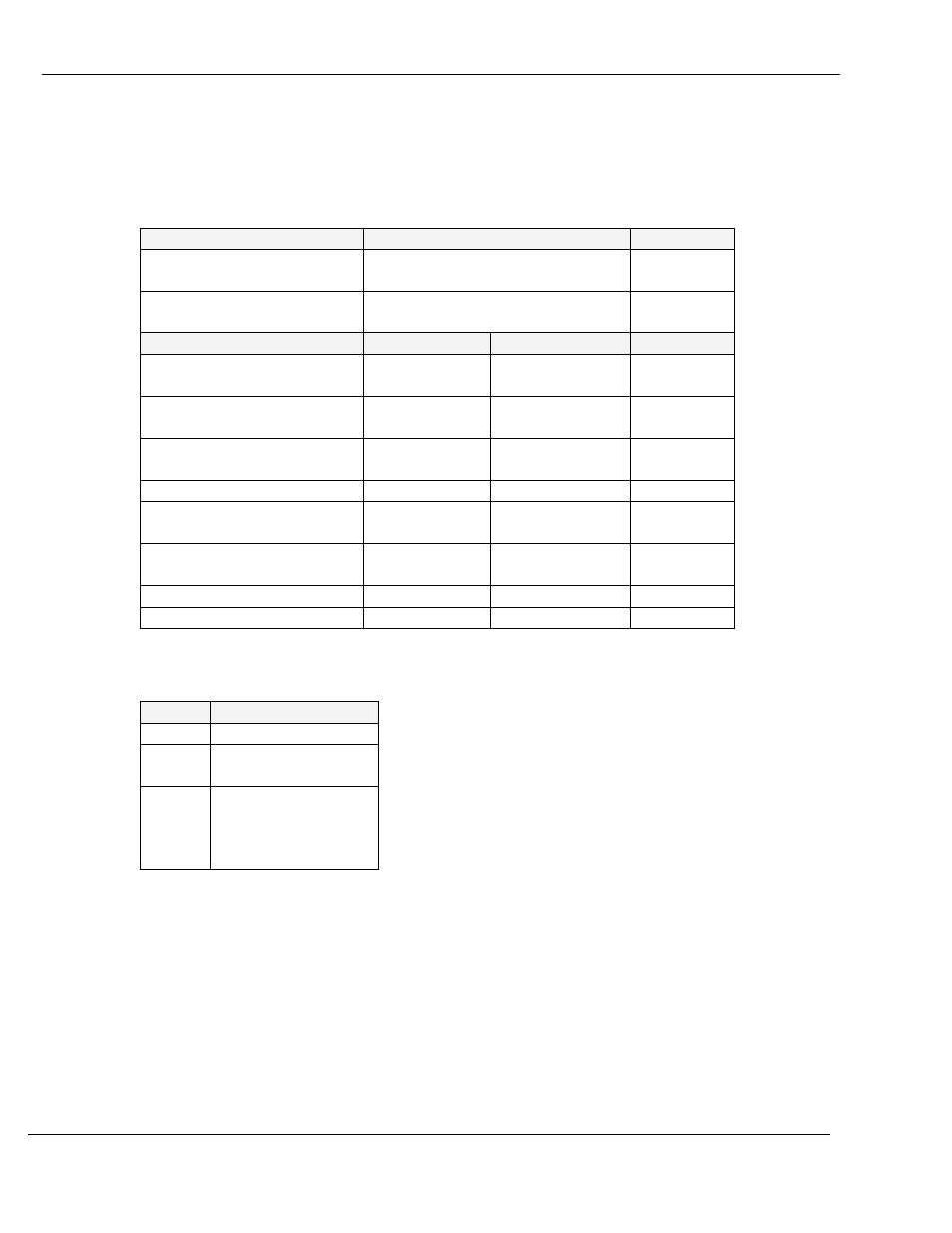
Configuration:
Use MAPware-7000 to assign input (X and XW), output (Y and YW), and configuration (M and MW) memory
addresses to the module. These addresses are created according to the slot location of the module, where nn refers
to the slot number:
Function
Register
Access
X0-X11 Inputs
X00000-011 (XW0000)
Rd Only
Y0-Y7 Outputs
Y00000-007 (YW0000)
Rd/Write
High Speed Counter Option
HSC Channel 1
HSC Channel 2
HSC Input
X1(terminal)
X00001 (reg)
X2(terminal)
X00002 (reg)
Rd Only
HSC Reset Input
X4(terminal)
X00004 (reg)
X5(terminal)
X00005 (reg)
Rd Only
HSC Output Flag
Y0(terminal)
Y00000 (reg)
Y1(terminal)
Y00001 (reg)
Rd/Write
HSC Configuration Register
MW0010
MW0020
Rd/Write
HSC Counter Register
(Current Value)
MW0011
MW0012
MW0021
MW0022
Rd/Write
HSC Preset Register
MW0013
MW0014
MW0023
MW0024
Rd/Write
HSC Enable Bit
M00240
M00400
Rd/Write
HSC Reset Bit
M00241
M00401
Rd/Write
Reference the table below when configuring each HSC Configuration Register (MW0010 and MW0020):
Bits
Function
15-4
Not used
3
0 : Falling Edge
1 : Rising Edge
2, 1, 0
Module Operating
Mode :
000 : Normal Operation
010 : Up Counter HSC
To implement High Speed Counter Operation:
1. Connect a device to X1 (Channel 1) or X2 (Channel 2) that will provide the high speed pulses to the
expansion module.
2. Configure for HSC mode using the configuration register MW0010 (Channel 1) or MW0020 (Channel 2).
3. Write the HSC preset count value in MW0013 (Channel 1) or MW0023 (Channel 2).
4. Enable the HSC by setting the HSC Enable Bit M00240 (Channel 1) or M00400 (Channel 2).
5. HSC increments (starting from 0) the current value register in MW0011 (Channel 1) or MW0021 (Channel
2) until the preset value is reached. Then HSC sets Y0 (Channel 1) or Y1 (Channel 2).