Teledyne LeCroy WaveLink Differential Probe Series (13-25 GHz) User Manual
Page 88
WaveLink Series Differential Probe (13-25 GHz)
82
WL-HBW-A-OM-E Rev B
Because the input signal of a differential amplifier is not referenced to ground, the concept of V
peak
versus V
peak-peak
may be confusing.
With a ground referenced signal, V
peak
is the maximum instantaneous voltage amplitude the signal
will have with respect to ground. In a differential system, there is no ground reference. Therefore,
the Differential Mode Range refers to the maximum instantaneous amplitude of the signal
difference between the positive input and the negative input. Since most amplifiers have
symmetrical bipolar inputs, the value is generally expressed as an absolute value, and can have
either polarity.
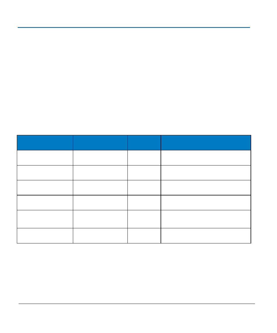
For example, an amplifier with a differential mode rating of ±1 V can have a maximum voltage
difference appearing at any instant in time of 1 V between the inputs. The polarity could be either
positive or negative. However, this does not imply that the number can be doubled to 2 volts. For
clarity, consider the following table of absolute voltages applied to the inputs of a WaveLink D1605
differential amplifier that has a differential mode range or ±800 mV and a common mode range of
±4 V:
Voltage on + input
to ground
Voltage on - input
to ground
Difference
Comment
+1.5 V
+0.8 V
+0.7 V
OK: within ±800 mV range
-1.5 V
-0.8 V
-0.7 V
OK: within ±800 mV range
+0.8 V
-0.1V
+0.9 V
Out of range: exceeds ±800 mV
+1.0 V
-1.0 V
+2.0 V
Out of range: exceeds ±800 mV
+6.5 V
+6.0 V
0.5 V
Exceeds ±4 V common mode range
1.5 V
pk-pk
sine
Ground
0.75 V
peak
OK: within ±800 mV range
Some amplitude is specified as peak to peak. The differential amplifier peak-to-peak range is twice
the peak differential mode range specification (at any instant in time) as the maximum voltage
amplitude signal is one-half of the peak-to-peak value.
In a balanced differential system, the signal on each output is an inverted copy of the other input.
For example, an LVDS system may have a pair of outputs, each of which has a voltage swing of 0 to
+370 mV. A logic 1 would be represented when the + output is at +370 mV, while the - output is at 0
V. A logic zero is the opposite polarity: the + output at 0 V and the - output at +370 mV. Note that