Functional test, Functional test overview, Test setup – Teledyne LeCroy WaveLink Differential Probe Series (13-25 GHz) User Manual
Page 60
WaveLink Series Differential Probe (13-25 GHz)
54
WL-HBW-A-OM-E Rev B
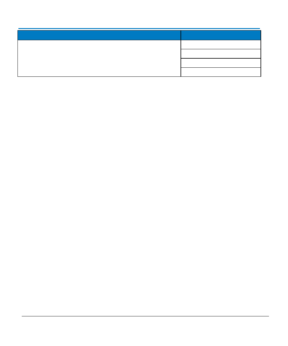
Service Option
Product Code
NIST Traceable Calibration with Test Data*
(one module)
D1305-A-CCNIST
D1605-A-CCNIST
D2005-A-CCNIST
D2505-A-CCNIST
*CCNIST NIST traceable calibration with test data is an available option for D1305-A, D1605-A,
D2005-A, and D2505-A probe tip modules only when ordered with either a WL-PLINK-A-CASE or WL-
2.92MM-CASE platform/cable assembly.
To learn more about these available service options, Contact Teledyne LeCroy for Support.
Functional Test
Functional Test Overview
The functional test can be used to verify the basic operation of the WaveLink Differential Probe
functions, using a Teledyne LeCroy X-Stream oscilloscope. Refer to the oscilloscope's online help for
proper use of the touch screen and controls.
Test Setup
Use the following steps to set up the basic tests:
1.
Connect an amplifier module to a platform/cable assembly (for example, a D1605-A to a WL-
PLINK-A), and then connect an interconnect lead to the amplifier module. Then connect the
platform/cable assembly to channel 1 of the oscilloscope. The instant the probe is connected
to the oscilloscope, the AutoColor ID LEDs should illuminate GREEN for less than 1 second
indicating the probe is compatible with the oscilloscope.
2.
After the green LED indication, the Probe AutoColor ID indicators illuminate in the color of the
channel to which the probe is connected. Verify the probe AutoColor ID indicates the proper
corresponding channel color by disconnecting the probe and reconnecting to the other
channels. Reconnect the probe to Channel 1.