Differential mode and common mode, Differential mode range and common mode range – Teledyne LeCroy WaveLink Differential Probe Series (13-25 GHz) User Manual
Page 87
Operator's Manual
WL-HBW-A-OM-E Rev B
81
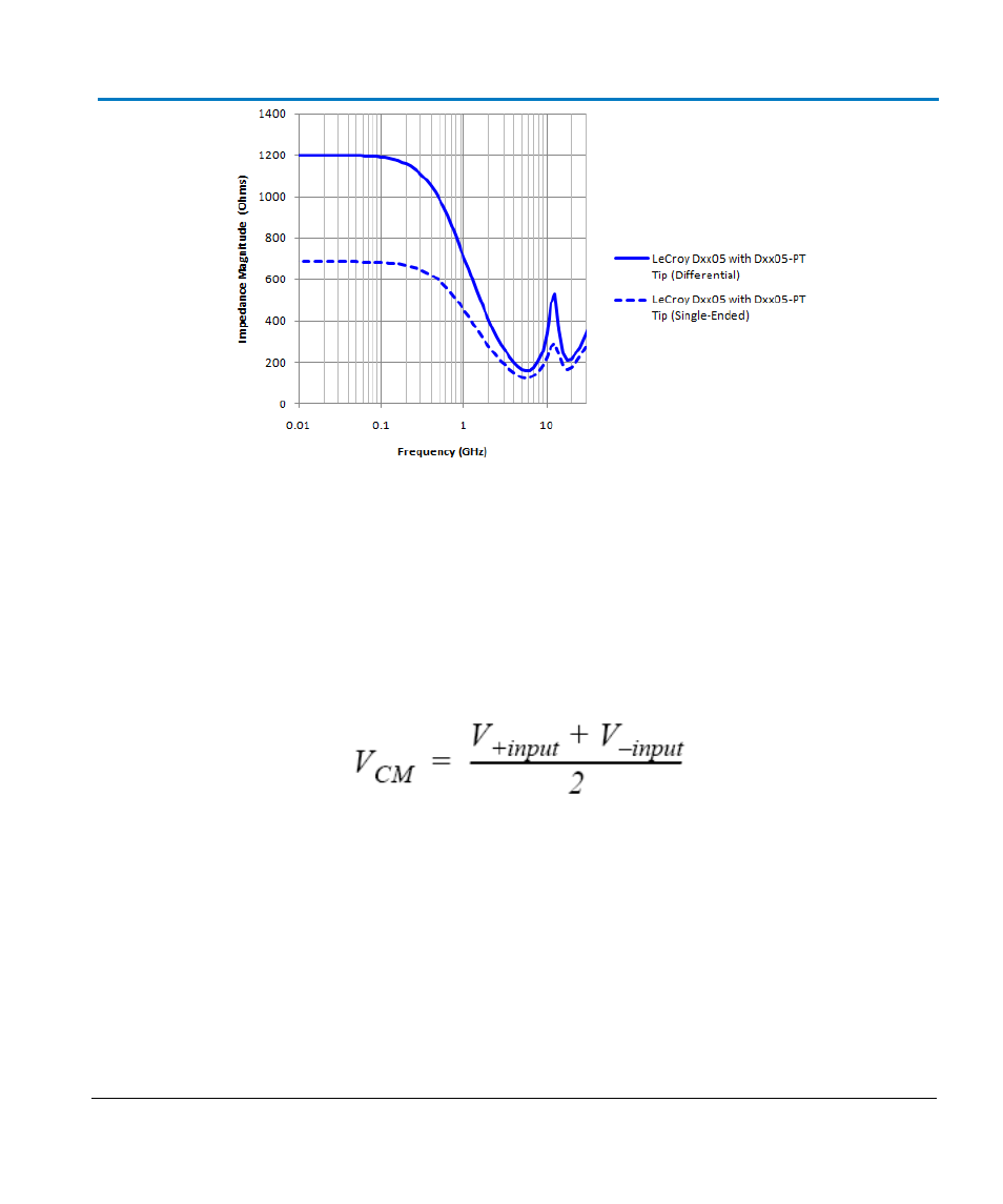
Typical probe input impedance magnitude as a function of frequency for differential and single-ended (one
lead grounded).
Differential Mode and Common Mode
Differential probes sense the voltage difference which appears between the + input and – input.
This voltage is referred to as the Differential Mode or Normal Mode voltage. The voltage component
which is referenced to earth and is identical on both inputs is rejected by the amplifier. This voltage
is referred to as the Common Mode voltage and can be expressed as:
Differential Mode Range and Common Mode Range
Differential Mode range is the maximum signal that can be applied between the + and - inputs
without overloading the amplifier/amplifier, which otherwise would result in clipping or distorting of
the waveform measured by the oscilloscope.
The Common Mode Range is the maximum voltage with respect to earth ground that can be applied
to either input. Exceeding the common mode range can result in unpredictable measurements.
Because the Common Mode signal is normally rejected, and not displayed on the oscilloscope, the
user needs to be careful to avoid accidentally exceeding the common mode range.