Teledyne LeCroy WaveLink Differential Probe Series (13-25 GHz) User Manual
Page 23
Operator's Manual
WL-HBW-A-OM-E Rev B
17
Do not use pliers or any other tools to tighten the collar. Remove the Amplifier Module by
loosening the threaded collar from the module and pulling the two assemblies apart.
By design, the amplifier module works with the WL-PLINK-A or WL-2.92MM
platform/cable assembly and either the Dxx05-SI Lead or Dxx05-PT Tip .
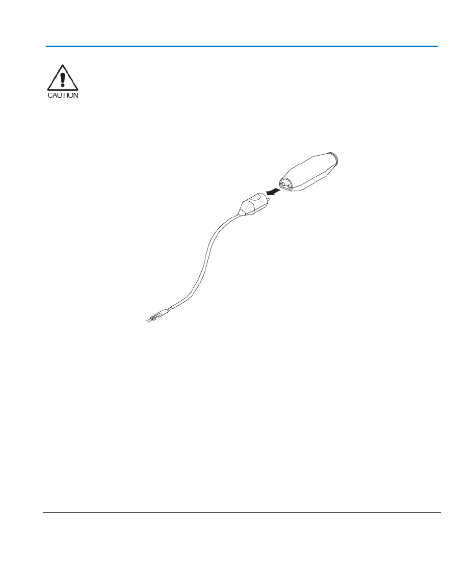
Connecting an Amplifier Module to an Interconnect Lead
Connecting a solder-in interconnect lead to an amplifier module. The positioner tip and other leads connect
in the same manner.
Align the flat side of the lead with the flat side of the amplifier module and press together.
NOTE:
Although interconnect leads for the
D1305-A, D1605-A, D2005-A, and D2505-A
mechanically mate with any module, they are only compatible with a
Dxx05 or
Dxx05-A
. No damage results; however, performance may be reduced when switching
leads between modules, and the response is not calibrated. Be sure to only use leads
with serial numbers that match with the differential amplifier module.
Different colors indicate different bandwidths and/or product classes. Avoid
accidental interchanging by matching the color coding of the interconnect lead tip
housing with the color of the corresponding amplifier module.