Connecting si interconnect leads to the fixture – Teledyne LeCroy WaveLink Differential Probe Series (13-25 GHz) User Manual
Page 72
WaveLink Series Differential Probe (13-25 GHz)
66
WL-HBW-A-OM-E Rev B
15.
Select the channel to which the BNC tee is connected and set the channel's sensitivity to 0.1
V/DIV. Verify that the input coupling is set to
DC
and the input resistance to
1 MΩ
.
Do not
terminate the BNC Tee adapter into 50 Ω
.
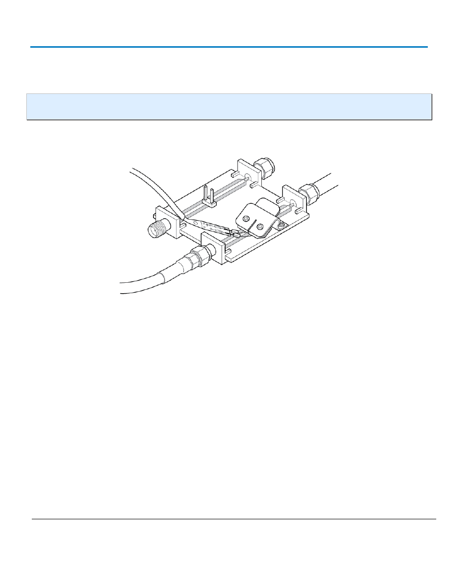
NOTE: The following step and figure show how to connect the interconnect lead to the deskew
fixture.
Connecting SI Interconnect Leads to the Fixture
SI to Deskew Fixture Connection
1.
The SI leads should be connected with the ends of the damping resistors placed under the
clip. Be sure to press down on the plastic tab to lift the clip and slide the wires under the clip,
verifying the
+
side is located over the center strip and the
–
side over the ground plane on
either side of the center strip. Release the tab. Set the DMM to read AC.
2.
Set the sine wave generator to about 70 Hz and the output 0.8 V
p-p
(0.282 V
rms
), as indicated
on the DMM.
3.
If necessary, adjust the SI tip in the fixture so the tips make good contact to get the proper
amplitude (about 4 divisions) on the oscilloscope.
4.
With good probe tip contacts verified, record the DMM reading to 1 mV resolution on the
Performance Verification Test Record (on
as
Probe Input Voltage
(step 4).
5.
Unplug the BNC to Banana Plug Adapter from the DMM and connect the Precision 50 Ω
Terminator to the DMM input (shown as follows).