Teledyne LeCroy WaveLink Differential Probe Series (13-25 GHz) User Manual
Page 29
Operator's Manual
WL-HBW-A-OM-E Rev B
23
SI L
EAD
A
TTACHMENT WITH
P
ROPER
S
TRESS
R
ELIEF
Using a small soldering iron tip, attach the free wires of the resistors to the appropriate test points
by carefully following the directions in the following sections.
The resistors are small in order to maintain high-frequency performance. However, they
are not sturdy enough to bear the weight of the probe module. It should be supported by
other means.
A positioning tool, such as the Platform/Cable Assembly Mounting Clamp, the Probe Tip Retaining
Clip, or EZ Probe positioner can be used to support the probe.
NOTE: The tip clip helps secure and reinforce the SI resistive tips. Best practice is to consistently
position the tip at the correct angle to the device under test which it is connected. Refer to Proper SI
Lead Positioning for more information. The solder-in lead provides better signal fidelity
performance with high frequency signals if it is elevated in this manner. The tip clip also helps to
secure and reinforce the SI resistive tips, and can position the resistor leads when soldering the
resistors to the test points.
SI
L
EAD
B
ENDING AND
S
OLDERING
P
ROCEDURE
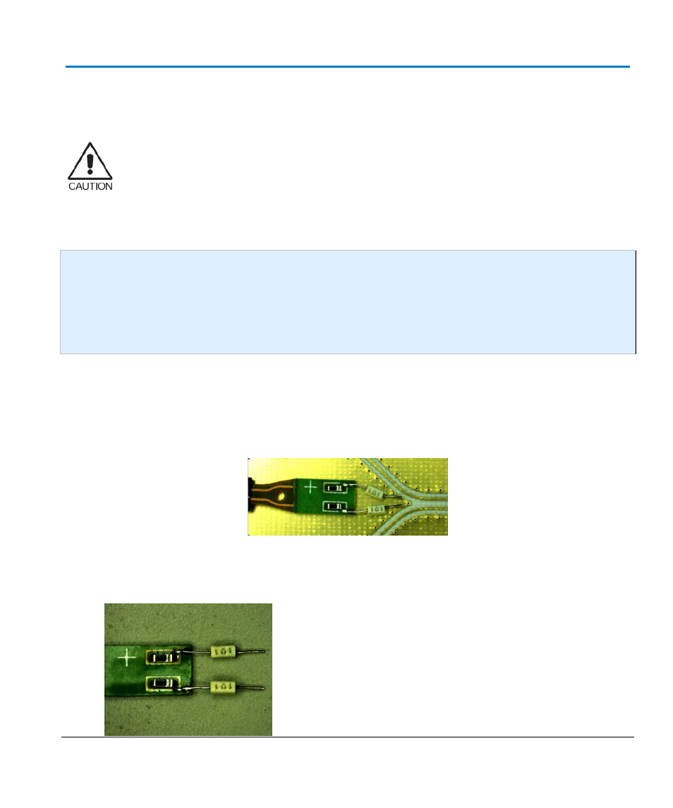
Properly bending the SI Lead tips results in a more consistent response. Upon first receiving your
SI Lead, the tips are not likely to be positioned for optimal performance when soldered to your
trace.
The goal is to get the resistor bodies to be parallel and the tips bent to sit on the test board traces.
1.
Bend the resistor bodies to position them parallel.