Connecting the probe to the test circuit – Teledyne LeCroy WaveLink Differential Probe Series (13-25 GHz) User Manual
Page 28
WaveLink Series Differential Probe (13-25 GHz)
22
WL-HBW-A-OM-E Rev B
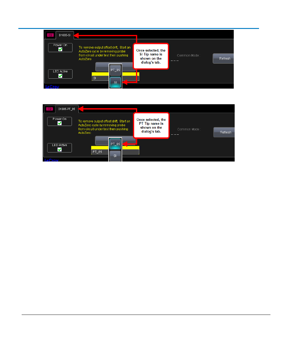
Tip selection showing the SI name on the dialog's tab.
Tip selection showing the PT name on the dialog's tab.
Connecting the Probe to the Test Circuit
For all amplifier modules and interconnect leads, positive voltages applied to the + input relative to
the – input deflects the oscilloscope trace towards the top of the screen.
Exercise care when connecting the probe to the test circuit to maintain the high frequency capability
of the probe in measurement applications. Increasing the parasitic capacitance or inductance in the
input path may introduce a ring, or slow the rise time of fast-rising signals. Any extension of the
signal path with extra wire leads, etc. adversely affects the probe's performance.
A ground connection is generally not required here. Refer to Probe Grounding (on page 27) for
more details.
Solder-in Interconnect Lead
The Solder-in Lead for the amplifier module is supplied with two pre-installed resistors, which are
intended to be soldered to the runs or pad test points on the board under test. Because the resistors
and the leads are small, this interconnect lead provides the maximum signal fidelity at the highest
frequency response.
Follow these instructions to ensure optimal response for your SI Lead.