IAI America PCON-CFA User Manual
Page 95
4. SCON-CA
89
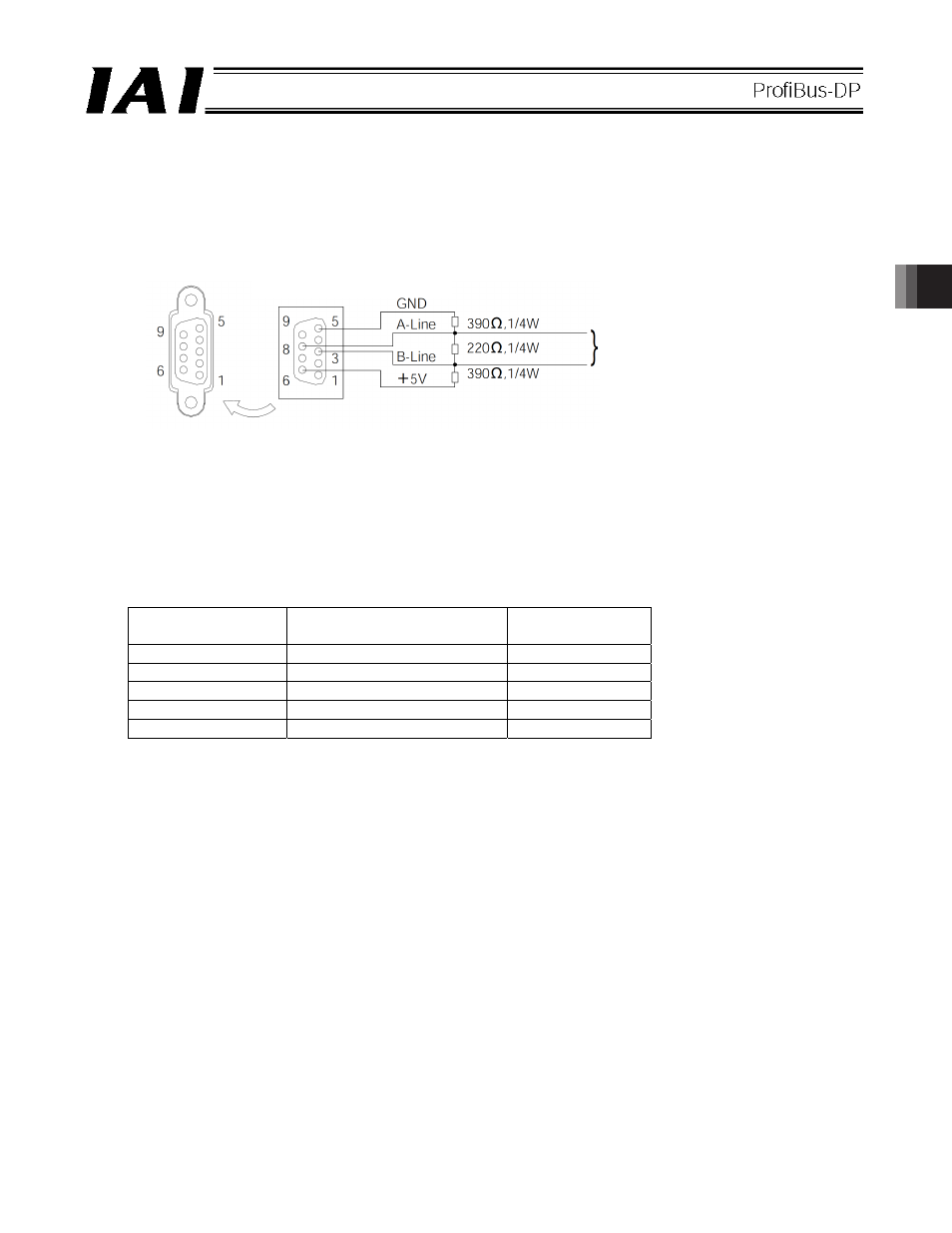
(3) Bus terminal processing
If the connector is to be connected to the network terminal node, connect the terminal resistor to the
PROFIBUS-DP communication connector as shown below or use a connector with terminal resistor.
z Example of connector with terminal resistor: SUBCON-PLUS-PROFIB/AX/SC (Phoenix Contact)
z Connecting the terminal resistor
(4) Operation mode selection (setting)
Set a desired operation mode using a parameter.
Set the mode selector switch on the front side of the controller to the MANU position, and then set parameter No.
84, “FMOD: Fieldbus operation mode” using the RC PC software (V6.00.05.00 or later). (Refer to 4.7,
“PROFIBUS-DP.”)
Note
Refer to operation manual of RC PC Software for the applicable version.
Set value
Operation mode
Number of
occupied bytes
0 (factory setting)
Remote I/O mode
2
1
Position/simple direct mode
8
2
Half direct mode
16
3
Full direct mode
32
4
Remote I/O mode 2
12
* If a greater value is entered, an excessive input error will occur.
(5) Node address setting (Refer to 4.7)
Set the node address using a parameter.
Set parameter No. 85, “NADR: Fieldbus node address” using the RC PC software.(Refer to 4.7, “PROFIBUS-DP
Parameters.”)
Settable range: 0 to 125 (The parameter has been set to 1 at the factory.)
(Note 1) Pay attention to duplicate node address settings.
(Note 2) PROFIBUS-DP node addresses are set with the master station always having address 0. Accordingly,
addresses of slave stations can be set between 1 and 125.
Board-end female
connector
Network-end male connector
(from counter-insertion side)
Network
wiring