IAI America PCON-CFA User Manual
Page 28
3. SCON-CA/CF
A
22
(1) PLC address configuration (* n indicates the initial input/output address for each axis.)
Parameter
No. 84
ACON/PCON DI
(port number)
PLC output address
ACON/PCON DO
(port number)
PLC input address
0
0 to 15
n
0 to 15
n
Pay attention to use of duplicate addresses.
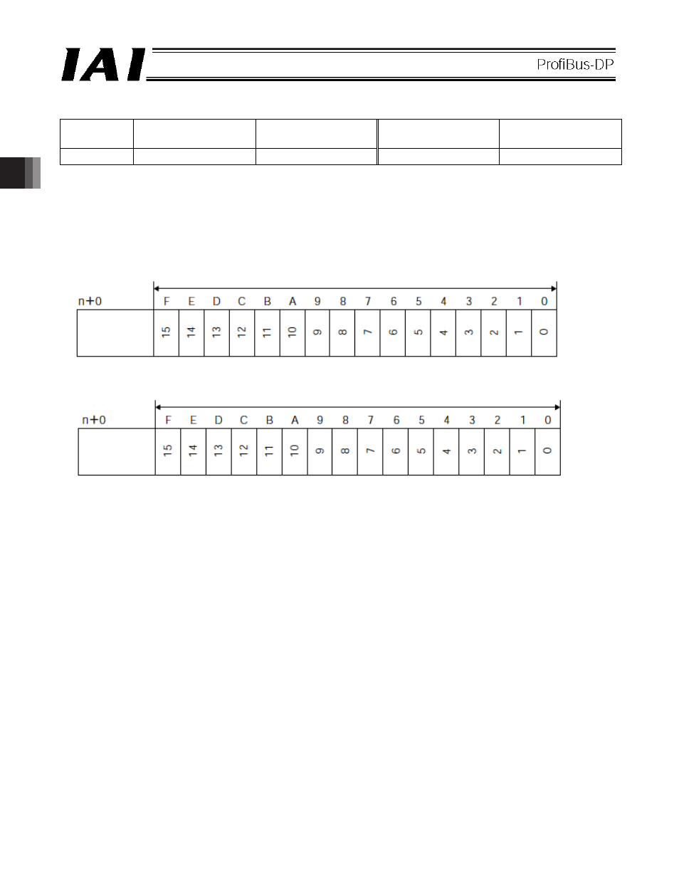
(2) I/O signal assignments for each axis
An I/O signal of each axis consists of 1 word (2 bytes) of I/O addresses.
z I/O addresses are controlled by bit ON/OFF signals from the PLC.
PLC output
address
PLC input
address
(* n indicates the initial output address for each axis.)
1 word = 2 bytes = 16 bits
1 word = 2 bytes = 16 bits
(* n indicates the initial input address for each axis.)
Controller
input port
number
Controller
output port
number