IAI America PCON-CFA User Manual
Page 221
5. Flow and Commands of Basic MECHA
TROLINK Communication
215
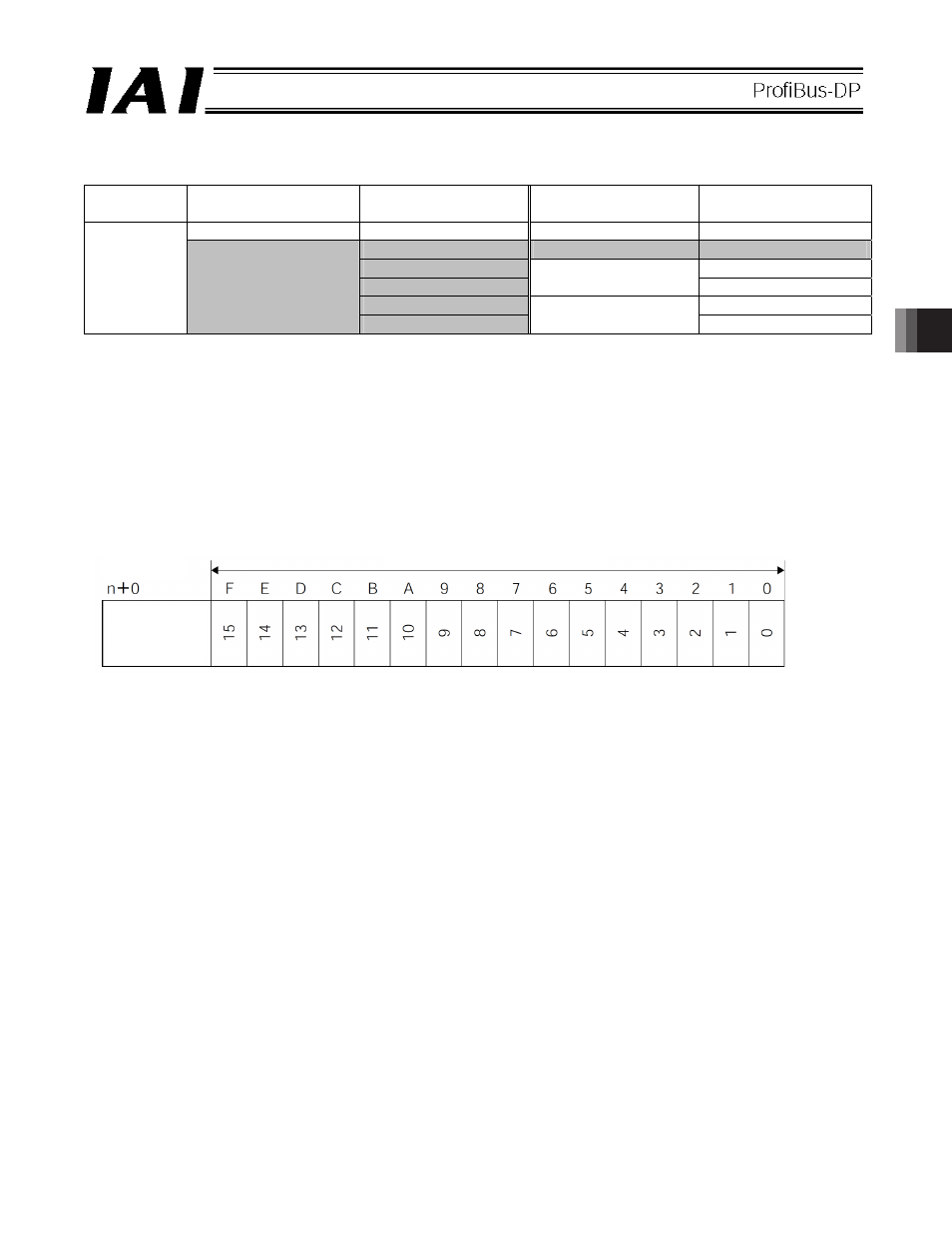
(1) PLC address configuration (* n indicates the initial input/output address for each axis.)
Parameter
No. 84
SCON-CA DI and input
register
PLC output address
SCON-CA DO and
output register
PLC input address
Port number 0 to 15
n+0
Port number 0 to 15
n+0
n+1
Occupied area
n+1
n+2 n+2
n+3
Current position
n+3
n+4 n+4
4
Occupied area
n+5
Force feedback data
n+5
(Note) The [occupied area] cannot be used for any other purpose.
Also pay attention to use of duplicate addresses.
(2) I/O signal assignments for each axis
An I/O signal of each axis consists of 6 words (12 bytes) of I/O addresses.
z Addresses controlled by port numbers are controlled by bit ON/OFF signals.
z The current position is a 2-word (32-bit) binary data (unit: 0.01 mm).
z The f
orce feedback data
is a 2-word (32-bit) binary data (unit: 0.01N).
PLC output
address
(* n indicates the initial output address for each axis.)
1 word = 2 bytes = 16 bits
Controller
input port
number