IAI America PCON-CFA User Manual
Page 182
5. Flow and Commands of Basic MECHA
TROLINK Communication
176
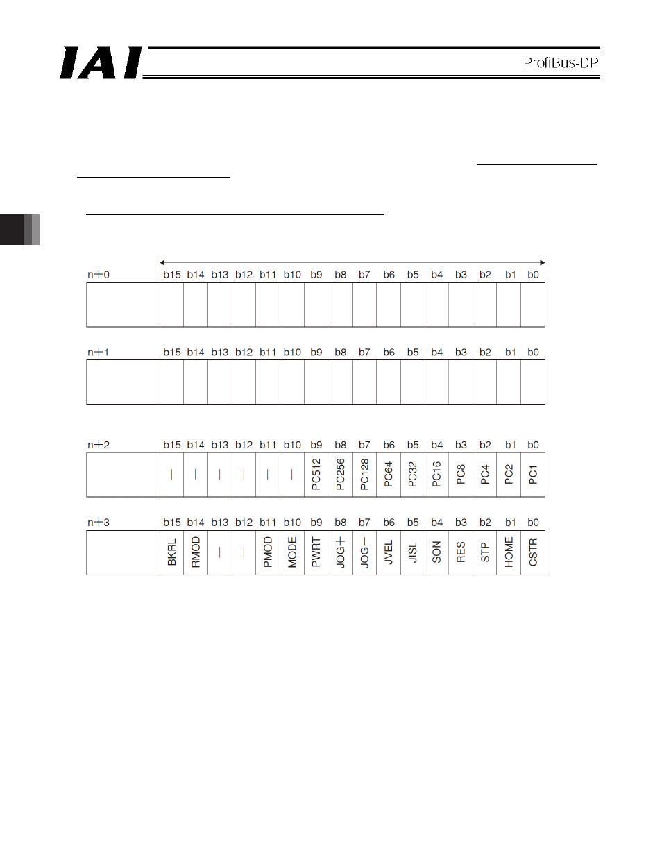
(2) I/O signal assignments for each axis
An I/O signal of each axis consists of 4 words (8 bytes) of I/O addresses.
z Control signals and status signals are bit ON/OFF signals.
z The target position and current position are both a 2-word (32-bit) binary data. Although values from -999999
to +999999 (unit: 0.01 mm) can be handled by the PLC, set position data within the software stroke range (0
up to the effective stroke length) of the applicable actuator.
z The specified position number and completed position number are both a 1-word (16-bit) binary data.
Although values from 0 to 767 can be handled by the PLC, use the PC software or teaching pendant to specify
a position number for which operation conditions are already set.
PLC output
address
(* n indicates the initial output address for each axis.)
1 word = 2 bytes = 16 bits
Target
position
(upper word)
Target
position
(lower word)
Specified
position
number
Control signal
If the target position is a negative value, it is expressed by a 2’s complement.