4 communication with the master station – IAI America PCON-CFA User Manual
Page 24
3. SCON-CA/CF
A
18
3.4
Communication with the Master Station
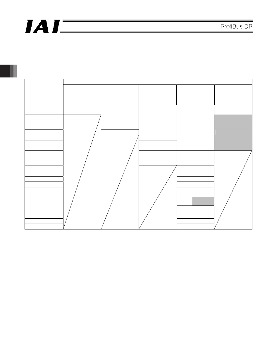
3.4.1 Operation Modes and Handling of PLC Addresses
The address assignments under each operation mode are shown below.
x PLC
output
o ACON/PCON input (* n indicates the initial output address for each axis.)
ACON/PCON DI and input data resister
Remote I/O
mode
Position/simple
direct mode
Half direct mode
Full direct mode
Remote I/O
mode 2
PLC output
address (word
address)
Number of
occupied bytes: 2
Number of
occupied bytes: 8
Number of
occupied bytes: 16
Number of
occupied bytes: 32
Number of
occupied bytes: 12
n
Port number
0 to 15
Port number 0 to
15
n+1
Target position
Target position
Target position
n+2
Specified position
number
n+3
Control signal
Positioning band
Positioning band
n+4
Speed
n+5
Acceleration/
deceleration
Speed
specification
Occupied area
n+6
Push-current
limiting value
n+7
Control signal
Zone boundary+
n+8
n+9
Zone boundary-
n+10
Acceleration
n+11
Deceleration
n+12
Push-current
limiting value
ACON
Occupied
area
n+13
PCON
Load
current
threshold
n+14
Control signal 1
n+15
Control signal 2
(Note) The “occupied area” is occupied according to the operation mode setting.
This area cannot be used for any other purpose. Also pay attention to use of duplicate addresses.