IAI America PCON-CFA User Manual
Page 214
5. Flow and Commands of Basic MECHA
TROLINK Communication
208
(2) I/O signal assignments for each axis
An I/O signal of each axis consists of 8 words (16 bytes) of I/O addresses.
z Control signals and status signals are bit ON/OFF signals.
z The target position and current position are both a 2-word (32-bit) binary data. Although values from -999999
to +999999 (unit: 0.01 mm) can be handled by the PLC, set position data within the software stroke range (0
up to the effective stroke length) of the applicable actuator.
z Set a desired positioning band. The positioning band is a 2-word (32-bit) binary data and values from 1 to
+999999 (unit: 0.01 mm) can be handled by the PLC.
z The speed is a 1-word (16-bit) binary data. Although values from 0 to +65535 (unit: 1.0 mm/sec or 0.1
mm/sec) can be handled by the PLC, set a value not exceeding the maximum speed of the applicable actuator.
Parameter No. 159, FB Half Direct Mode Speed Unit, determines the unit of measure.
Parameter No.159 setting value
Speed setting unit
0 1.0
mm/sec
1 0.1
mm/sec
z The acceleration/deceleration is a 1-word (16-bit) binary data. Although values from 1 to 300 (unit: 0.01 G) can
be handled by the PLC, set a value not exceeding the maximum acceleration and maximum deceleration of
the applicable actuator.
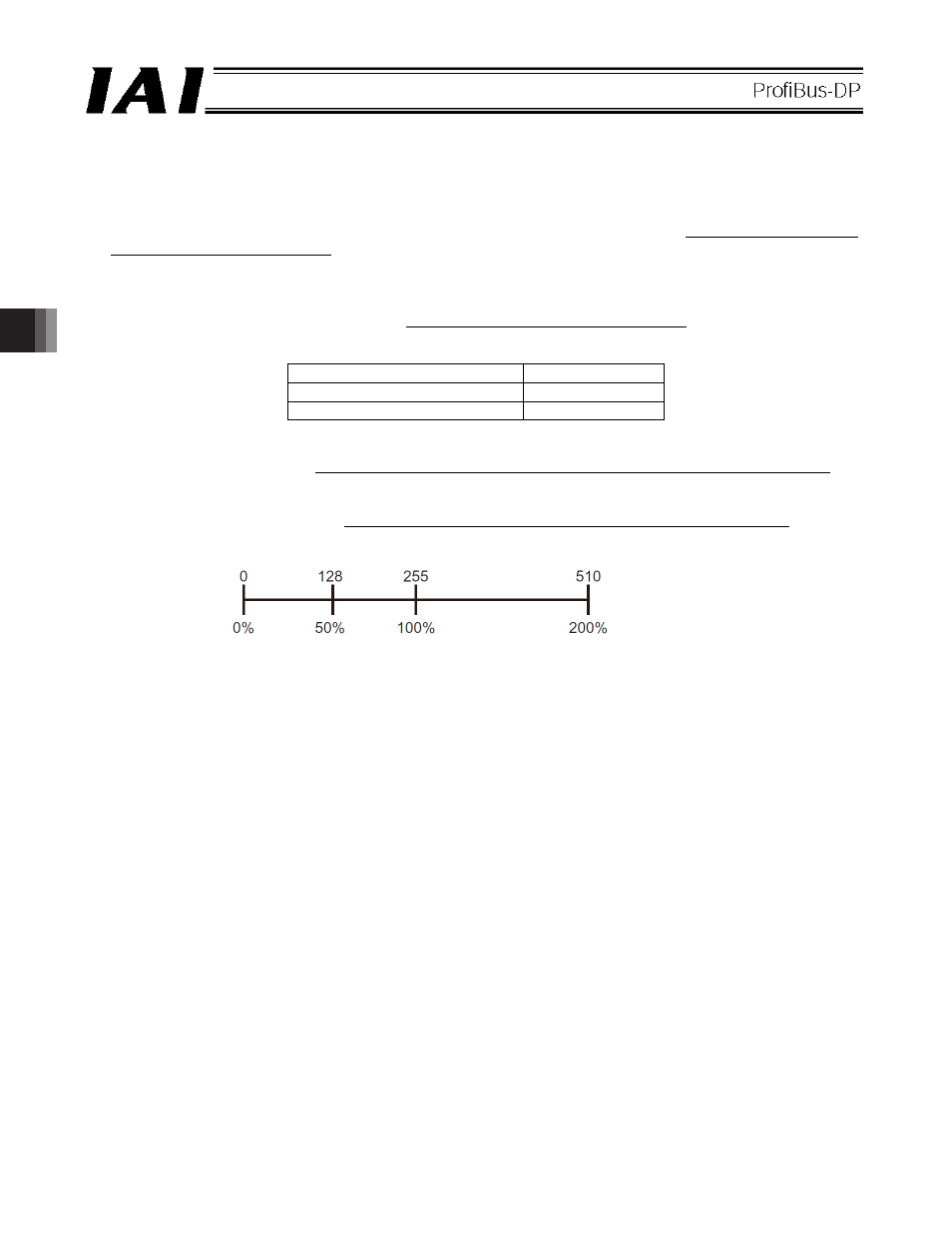
z The push-current limiting value is a 1-word (16-bit) binary data. Although values from 0 (0%) to 255 (100%)
can be handled by the PLC, set a value within the specifiable range of push-current limiting values of the
applicable actuator (refer to the catalog or operation manual for the actuator).
z The force feedback data is 2-word (32-bit) binary data (unit: 0.01 N).
z The current position is 2-word (32-bit) binary data (unit: 0.01 mm/sec).
z The alarm code is a 1-word (16-bit) binary data.
Set value
Push-current
limiting value