IAI America PCON-CFA User Manual
Page 25
3. SCON-CA/CF
A
19
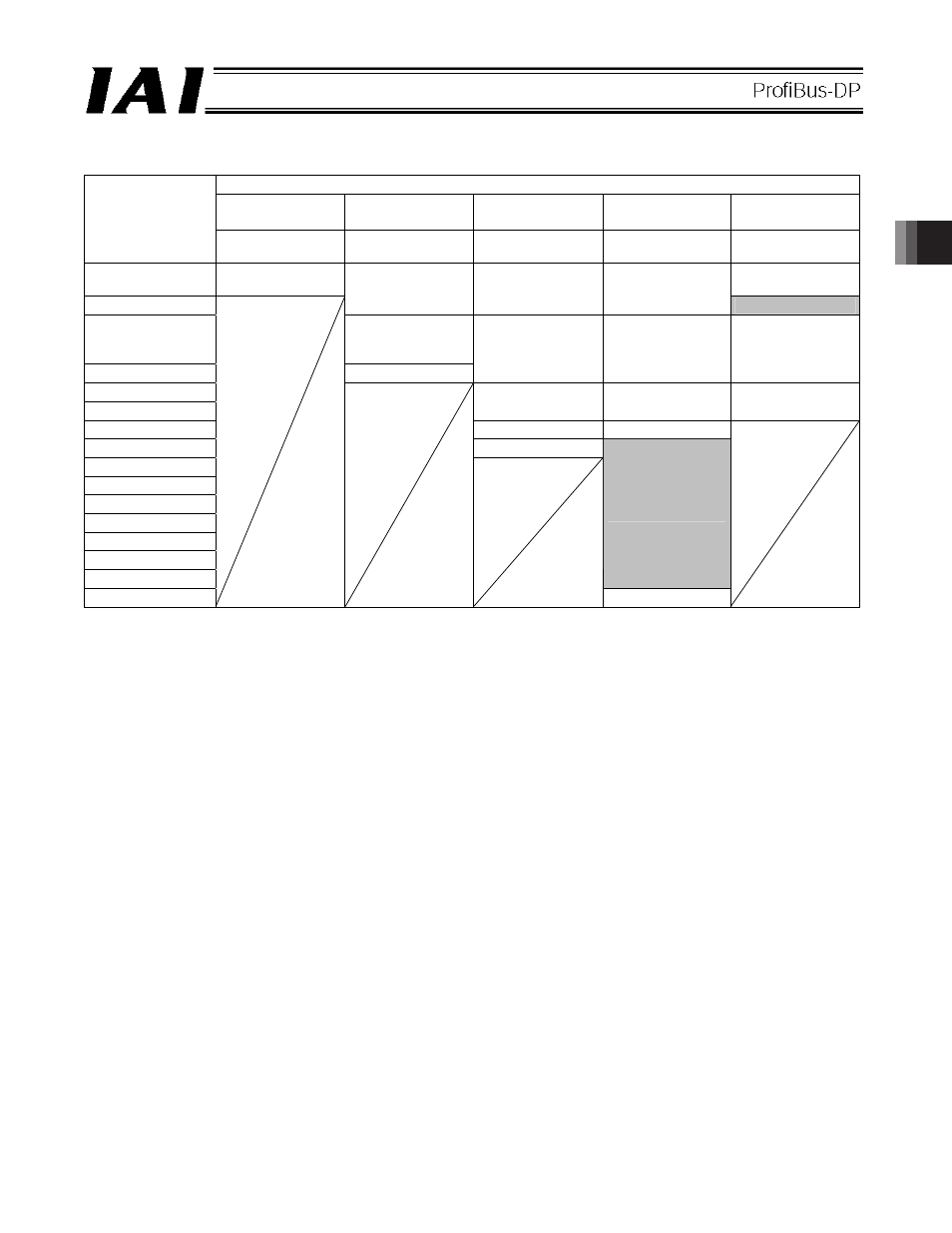
x ACON/PCON
output
o PLC input (* n indicates the initial input address for each axis.)
ACON/PCON DO and output data resister
Remote I/O
mode
Position/simple
direct mode
Half direct mode
Full direct mode
Remote I/O
mode 2
PLC input
address (word
address)
Number of
occupied bytes: 2
Number of
occupied bytes: 8
Number of
occupied bytes: 16
Number of
occupied bytes: 32
Number of
occupied bytes: 12
n
Port number 0 to
15
Port number 0 to
15
n+1
Current position
Current position Current
position
Occupied area
n+2
Completed position
number
(simple alarm ID)
n+3
Status signal
Command current
Command current
Current position
n+4
n+5
Current speed
Current speed Command
current
n+6
Alarm code
Alarm code
n+7
Status signal
n+8
n+9
n+10
n+11
n+12
n+13
n+14
Occupied area
n+15
Status signal
(Note) The “occupied area” is occupied according to the operation mode setting.
This area cannot be used for any other purpose. Also pay attention to use of duplicate addresses.