Ronan X11CA Software Manual User Manual
Page 37
Rev 1.3 Series X11CA Computer Annunciators: X11CA Configuration Software User’s Manual
4. X11CA Software Operation
Hardware Control-© 2003 Ronan Engineering
33
Normally Energized option for the relay output
When FC, ACK, ALARM or HORN is chosen for the relay-
triggering signal, the Normally Energized check box becomes
activated. By default, the relay output is set to Normally Not-
Energized. When this box is checked, the state of an event gets
reversed, so that it stays active in its normal state, but inactive in
its alarm state. Check the Auxiliary board (Part NO: X11-1049) for
jumper settings.
Dual Output option for the relay output
This option is available in the future. Once this option is activated,
the Auxiliary A signal from the micro controller activates both the
relays A and C, the Auxiliary B signal activates both the relays B
and D.
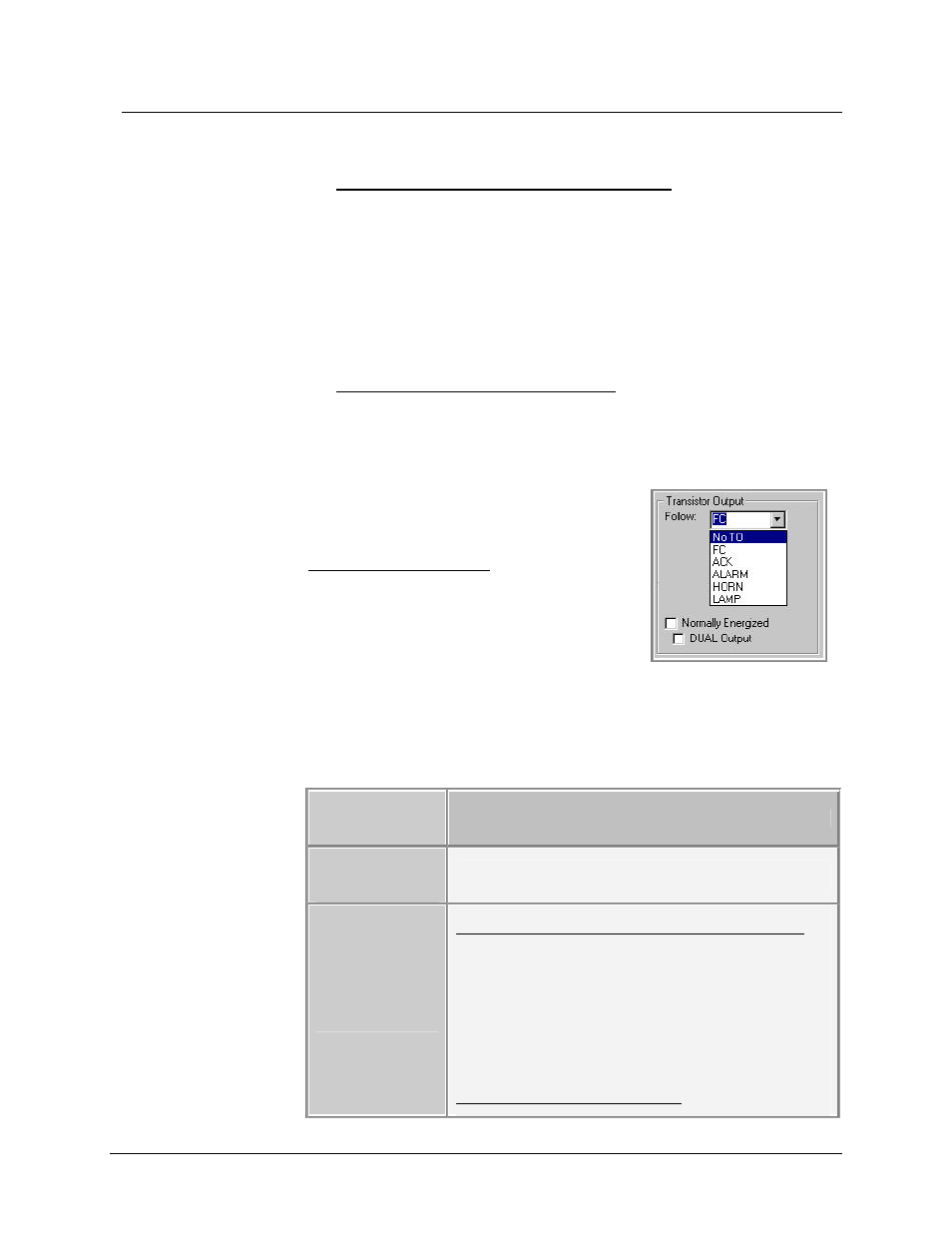
? TRANSISTOR OUTPUT
Choose the signal that will trigger the
Transistor Output signal from X11CA-
IM. The outcome depends on the
sequence type of each channel.
Figure 4-20 Transistor
Output Follows
The following is the sequence of reaction for A-1 type.
Signal to Trigger
Transistor
Output
Description
No TO
(No Transistor
Output)
The signals are ignored and not displayed.
FC
(
Field Contact
)
If the Field Contact input is not normally energized
:
§ When the Field Contact goes into an
alarm condition, transistor output turns
ON
§ When the Field Contact returns to normal
condition, transistor output turns OFF.
If the input is normally energized