Ronan X11CA Software Manual User Manual
Page 31
Rev 1.3 Series X11CA Computer Annunciators: X11CA Configuration Software User’s Manual
4. X11CA Software Operation
Hardware Control-© 2003 Ronan Engineering
27
until the alarm is acknowledged. After that, the
alarms return to normal and then reset.
Table 4-13 Signals the Serial Data Output Follows
After setting System properties, click on the OK button.
E
E
x
x
a
a
m
m
p
p
l
l
e
e
:
:
F
F
i
i
g
g
u
u
r
r
e
e
4
4
-
-
1
1
(
(
M
M
o
o
d
d
u
u
l
l
e
e
1
1
:
:
3
3
c
c
h
h
a
a
n
n
n
n
e
e
l
l
s
s
,
,
M
M
o
o
d
d
u
u
l
l
e
e
2
2
:
:
4
4
c
c
h
h
a
a
n
n
n
n
e
e
l
l
s
s
)
)
X
X
1
1
1
1
C
C
A
A
-
-
I
I
M
M
S
S
w
w
i
i
t
t
c
c
h
h
:
:
P
P
R
R
G
G
M
M
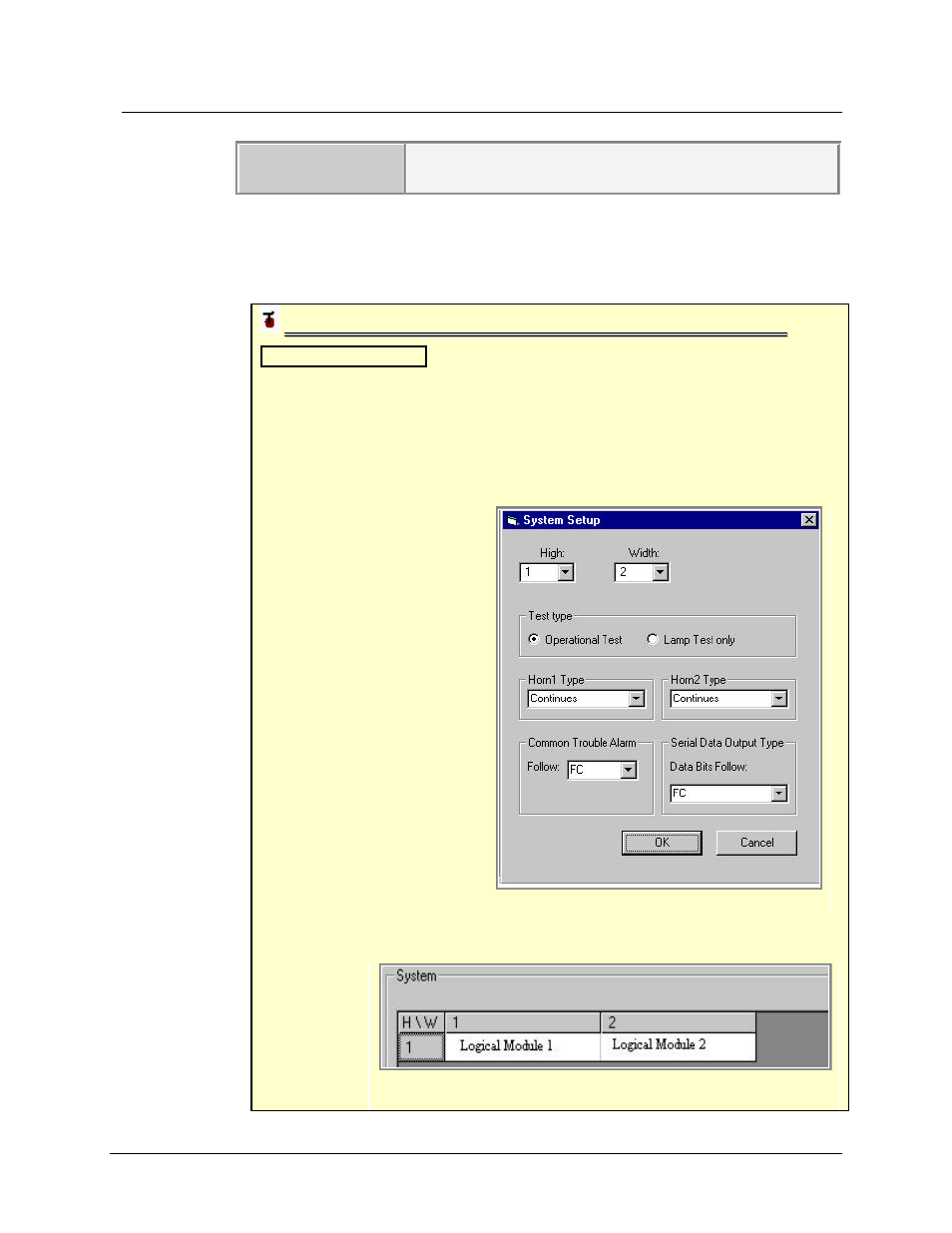
For example, you have two modules in the X11CA chassis, and the addresses
of the modules are set to 1 and 2. You need to set up two cells in the table as
shown in Figure 4-12 Setting Up Two Modules. Set the Width and the High
to 2 and 1, respectively. Select the Operational Test type and leave the horn
types alone. Set both the CTA triggering signal and Serial Output type to FC.
Click on the OK button.
Figure 4-12 Setting Up
Two Modules
The table contains two logical module cells; as shown in the Figure 4-13 A
Table with Two Logical Modules.
Figure 4-13
A Table
with Two
Logical
Modules