Ronan X11CA Software Manual User Manual
Page 21
Rev 1.3 Series X11CA Computer Annunciators: X11CA Configuration Software User’s Manual
4. X11CA Software Operation
Hardware Control-© 2003 Ronan Engineering
17
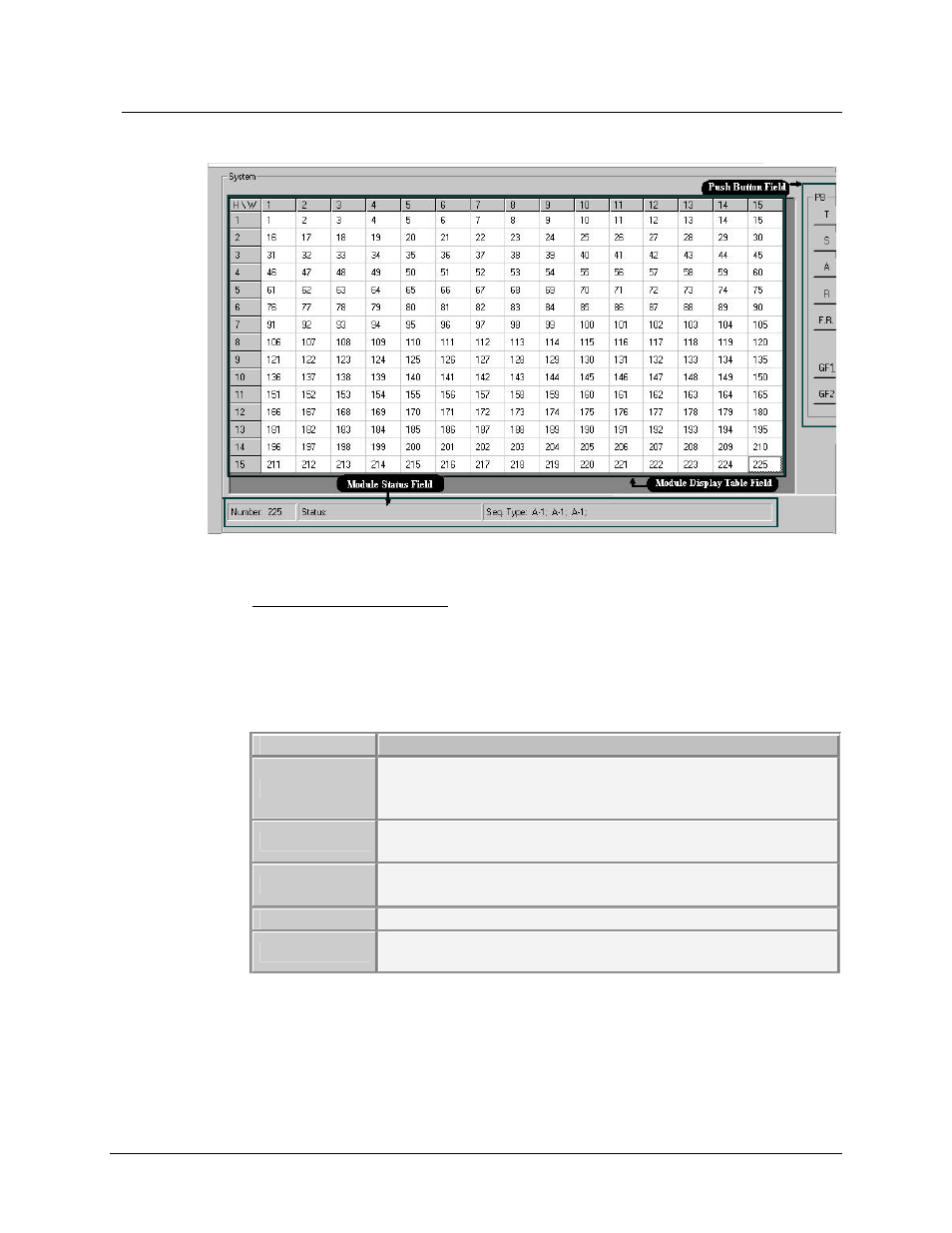
Figure 4-7 System Display Field
1) Module Display Table Area
Each cell on the table represents a logical module with a unique address that is
same as its physical address. A status message of the logical module, such as
No Comm., Run, Stop, Erased or Programmed, can be displayed in the cell.
The following table has descriptions of each message.
Messages
Descriptions
NoComm
There is no communication between the logical module and its
physical module. The alarm board could be either missing or
inactive, or the connection is bad.
Run
Connection between the logical module and its physical module
is active, and the physical module is ready for testing.
Stop
Configuration Software
stopped simulating the field contact
inputs onto the physical module.
Erased
Firmware of the physical module was cleared.
Programmed
Saving properties of the logical module into its physical alarm
module was completed.
If a cell is clicked once, the selected module cell is highlighted, and its module
number, its status, and sequence types of its channels display on the Module
Status area.