Ronan X11CA Software Manual User Manual
Page 25
Rev 1.3 Series X11CA Computer Annunciators: X11CA Configuration Software User’s Manual
4. X11CA Software Operation
Hardware Control-© 2003 Ronan Engineering
21
3) To retrieve physical module properties to the logical modules, Section
4.4.1.Setting System Properties, Section 4.6 Connecting to Physical Alarm
Modules, and then Section 4.4.7
Retrieving Properties from a Configuration
File.
Before you start configuring the system and module properties, it is better to get all
the information.
§ The number of physical modules.
§ The number of channels for each module.
§ The test type. (Refer to Section 4.4.1 Setting System Properties.)
§ The type of horns. (Refer to Section 4.4.1 Setting System Properties.)
§ The signal that Common Trouble Alarm follows. (Refer to Section 4.4.1 Setting
System Properties.)
§ The signal that the serial data output follows. (Refer to Section 4.4.1 Setting
System Properties.)
§ Inhibit signals for the Global Function tests for each module if there is any.
(Refer to Section 4.4.2.1 Setting the Common Signals Field.)
§ The sequence type of each channel. (Refer to Section 4.5.2.1
Setting
Channel Properties.)
§ Field Contact time delay. (Refer to Section 4.5.2.1 Setting Channel Properties.)
§ The signal that will trigger Auxiliary Relay Output each channel. (Refer to
Section 4.5.2.1
Setting Channel Properties.)
§ The signal that will trigger Transistor Output follows for each channel. (Refer to
Section 4.5.2.1
Setting Channel Properties.)
§ Whether or not Auxiliary Relay Output is normally energized. (Refer to Section
4.5.2.1
Setting Channel Properties.)
§ Whether or not Transistor Output is normally energized. . (Refer to Section
4.5.2.1
Setting Channel Properties.)
4.4.1 Setting System Properties
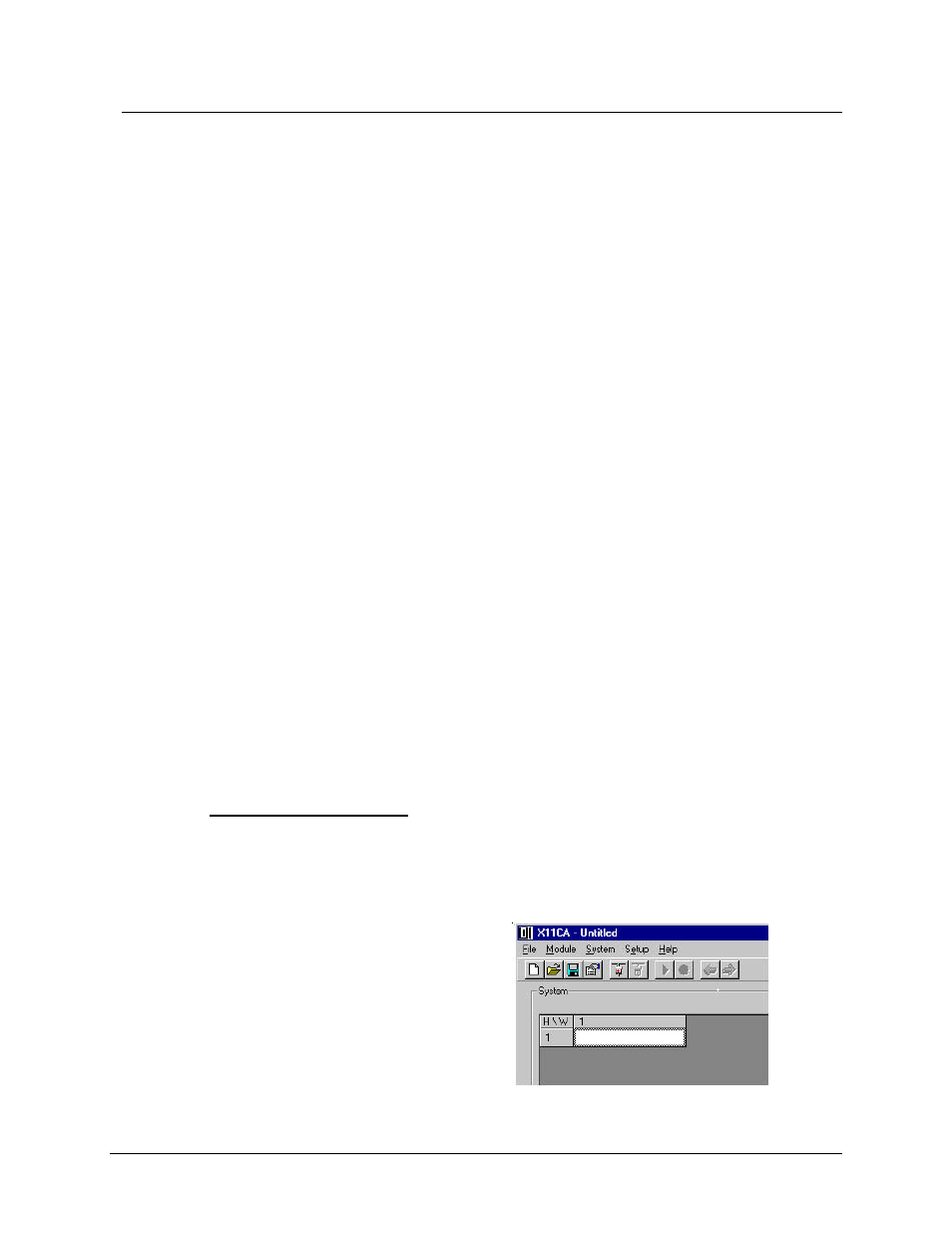
When the Configuration Software opens, the System display area will show the
Module table in the default setting, which is one logical module at the cell position
[1,1].
Figure 4-10 Logical Module 1