Ronan X11CA Software Manual User Manual
Page 22
Rev 1.3 Series X11CA Computer Annunciators: X11CA Configuration Software User’s Manual
4. X11CA Software Operation
Hardware Control-© 2003 Ronan Engineering
18
If it is double clicked, it opens its Module Properties window where you can
view or modify properties of the logical module
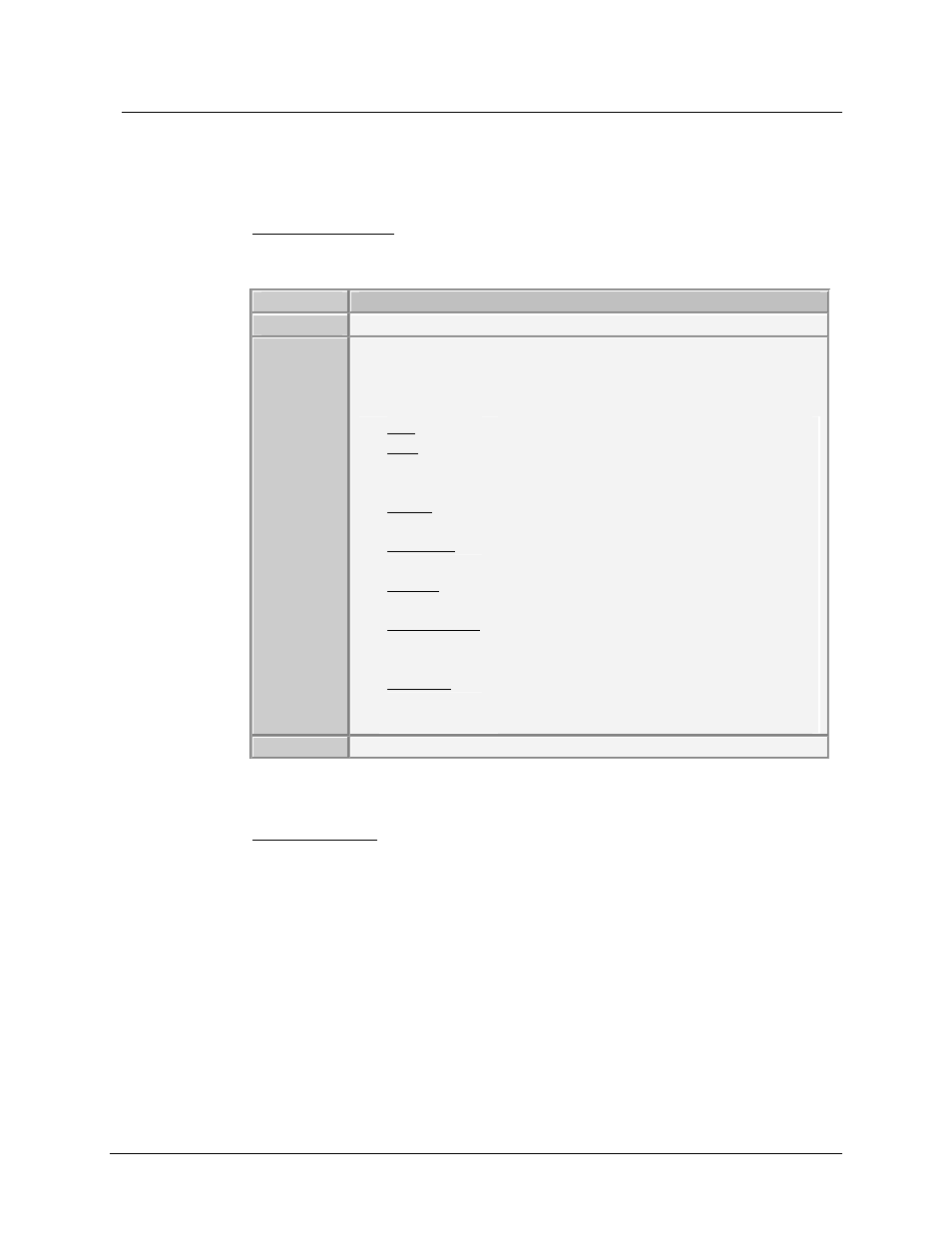
2) Module Status Area
This area displays following information for a selected module.
Descriptions
Number
The address of the logical module.
Status
The status of communication between each logical module and its
physical module, such as Run, Stop, Ready, Receiving, Erasing,
Verifying or Programming,
Run
: The physical module is ready to be tested.
Stop
: The physical module is ready to be
programmed or send copy of its properties to
its logical module.
Ready
: The logical module is ready for the next
action.
Receiving
: The logical module is receiving data from
the physical module.
Erasing
: Properties of the physical module are being
ceared.
Programming : The logical module is in the process of
copying its properties to the physical alarm
module.
Verifying
:
Configuration Software
is checking if the
data in the physical module is same as the
one in its logical module.
Seq Type
Sequence types of the logical module channels.
Table 4-7 Module Status Area
3) Push Button Area
This area is not visible until the Connect function is activated. Once
activated, it displays seven push buttons for testing the operations and lamp
display functions: Test, Acknowledge, Reset, Silence, F.R, GF1 and GF2.
These buttons are used to test physical alarm module properties. How to test
the modules are covered in Section 4.11Testing Alarm Modules .