Ronan X54-3412 User Manual
Ronan Equipment
Page 1 of 2
Rev. 0
A Family of
Products!!!
Transmitters
Alarm Trips
I/I Isolators
Ronan Engineering Company
Ph: 800-327-6626 Fax: 818-992-6435 E-mail: [email protected] Web: www.ronan.com
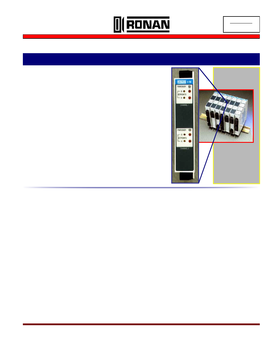
♦ High Density Dual Channel Packaging
♦ Field Configurable Options Including:
(6) T/C types, volt, mV or mA inputs + (7) std. input spans
with selectable zero offsets
♦ Full Input/Output/Power and Channel Isolation
♦ Front Panel Power/Sensor Fail LED Indicator
♦ Front Access to Zero, Span and Setpoint Controls
♦ Standard 35 mm DIN Rail Mounting
DESCRIPTION:
The X54-3412 is a dual channel alarm trip pow-
ered by 24 vdc. Features include: two piece plug-in connectors for easy
wiring and maintenance; Power/Sensor Fail LEDs; field configurable
ranges and input types; 1000 vac isolation; and front panel ZERO,
SPAN, and setpoint adjustments. RFI protection, wide operating tem-
perature, and high accuracy are standard. Dual setpoints are user con-
figured for high or low and have adjustable deadband. Output relays
are form “C” and can be normally energized or de-energized. Custom
inputs, outputs, and scaling are available from the factory.
Universal Alarm Trips - Field Configuration Options - High Density DIN Rail Mount
X54-3412
Dual Channel Thermocouple, mV, Volt, mA Alarm Trip
ISO 9001
REGISTERED
SPECIFICATIONS:
Input:
Thermocouple type E, J, K, T, R, S, or mV, volt, and mA
(Factory or field configurable)
Input Ranges: Standard factory ranges or field configurable to
application requirements
Input Impedance:
T/C or mV > 100 Mohm; volts = >550 K ohm;
mA = 10 ohm
Setpoint Adjustment:
Front-accessible, multi-turn, infinite resolution potentiometer
2 setpoints per channel. Field select normally energized or
de-energized and high or low setpoint relay operation.
Setpoint Repeatability: +/- 0.1% of span
Alarm Indication:
Front panel Red LED for each setpoint
Power On/Sensor Failure Response:
Green “Power On” LED turns Red if sensor fails. Up scale
drive on sensor failure is standard.
Response Time: 100 milliseconds.
Hysteresis:
Internal adjustments provide deadband adjustment from ap-
proximately 1-15% of range.
Contact Outputs:
One set of normally open and closed contacts per setpoint.
Contact Rating:
standard relays = 0.6 amps at 125 vac or 110 vdc, 2 amps at
30 vdc, (resistive loads)
optional relays = 14 amps at 120 vac, 10 amps at 240 vac, 8
amps at 24 vdc (resistive load; meets international standards)
Isolation: 1,000 V between channels.
Common Mode Voltage:
1000 volts peak AC maximum without damage.
Radio Frequency Effects:
< 0.4 mV (referred to input) + 0.2% of span (referred to out-
put) when exposed to 5W transmitter with frequency range
20-460 MHz at a distance of 1 m.
Ambient Temperature Range:
Operating: -20 to 158
°
F (-25 to 70
°
C).
Storage: -40 to 158
°
F ( -40 to 70
°
C).
Power Supply Range:
18 to 30 VDC. (max. alarm state current = 190 mA@ 24 vdc)
Terminals:
High temperature polyester type, wire size 12 AWG max., 10
amps max., 300 V max.
Specifications apply at 23 +/- 2°C (74 +/- 2°F) unless otherwise specified, and are subject to change without notice,