Micromod MOD: 30MLTraining Manual User Manual
Page 94
Training Manual
PID Loop Lab
6.3.2 Configuring the blocks:
11.
Let us configure these blocks next.
• Configure the Analog Input block.
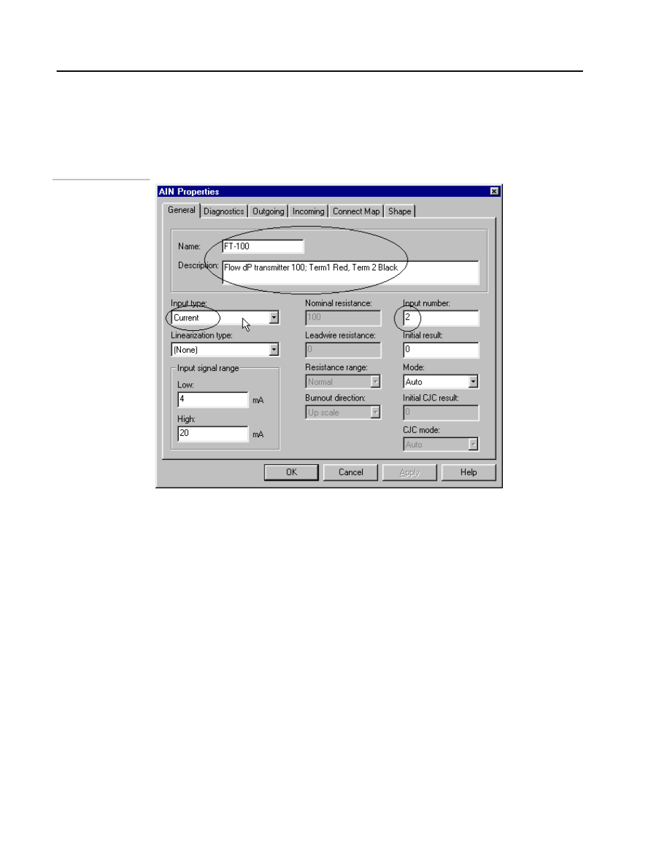
• Double-click on the AIN block to open its Properties menu as shown below:
Figure 6 .19.
AIN Block
• Type FT-100 as the name.
• Select Current as the Input type from the drop-down menu.
• Type the Input number as 2 and Description as shown in the above figure. This is
the built-in input 2 of the MOD 30ML. Note that changing the input type changes
the Input Low and High signal ranges automatically. This can also be manually
changed.
• Click on OK when done.
If you are using the MOD 30ML Demo box, leave the Input type as Volts in the above
configuration. Specify the Input signal range as 1 to 5 Volts.
• Configure the VCI block: Double-click on the VCI block. We will configure this
to specify the input function for the analog input configured above. The VCI block
Properties will open as shown in the next figure:
6 - 14