Micromod MOD: 30MLTraining Manual User Manual
Page 172
Training Manual
Peer-to-Peer Communications
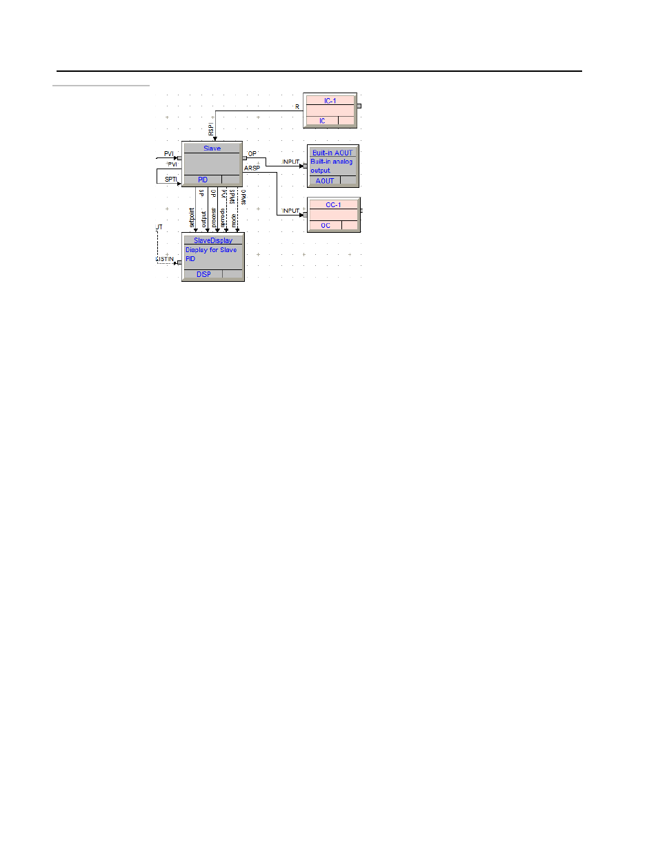
Connecting blocks
5.
Configure another Output Communications Block:
• Place another OC block and configure it to send the PID block’s TS (track status) to IC2 of the
first instrument. Note that this will be a Discrete signal.
• Compile and download your database to instrument 2.
6.
Connect the ICN:
• Devices on an ICN are wired in parallel, with the +/- using one pair of wires and
24V/Com using the other pair.
• The terminals required for this exercise are as follows:
15: 24Vdc
14: COM
13: +
12: -
• Each ICN requires one terminator. The terminator is to be installed into the same
terminals as the ICN wires on one of the instruments. Because the terminator has
solid wires, care must be taken to ensure that both it and the ICN wires are secured
into the terminal.
7.
Test your configurations for proper operation:
• Look for ICN errors “Not Receiving Data” on either instrument.
• In normal operation, both controllers are in Auto mode, the Master is using a Local
Setpoint and the Slave is using a Remote Setpoint.
• Placing the Slave controller into Manual, or changing its Setpoint mode to Local
should force the Master controllers into Track mode.
10 - 16