Set handing, Pring, Hysical – Controlled Products Systems Group STRONGARMPARK DC 10 User Manual
Page 74: Ever, Ssembly
7-2
D0536 Rev. B
StrongArmPark DC: Programming & Operations Manual
www.hysecurity.com
s
prIng
& p
HYsICal
s
top
l
ever
a
ssemBlY
12
7
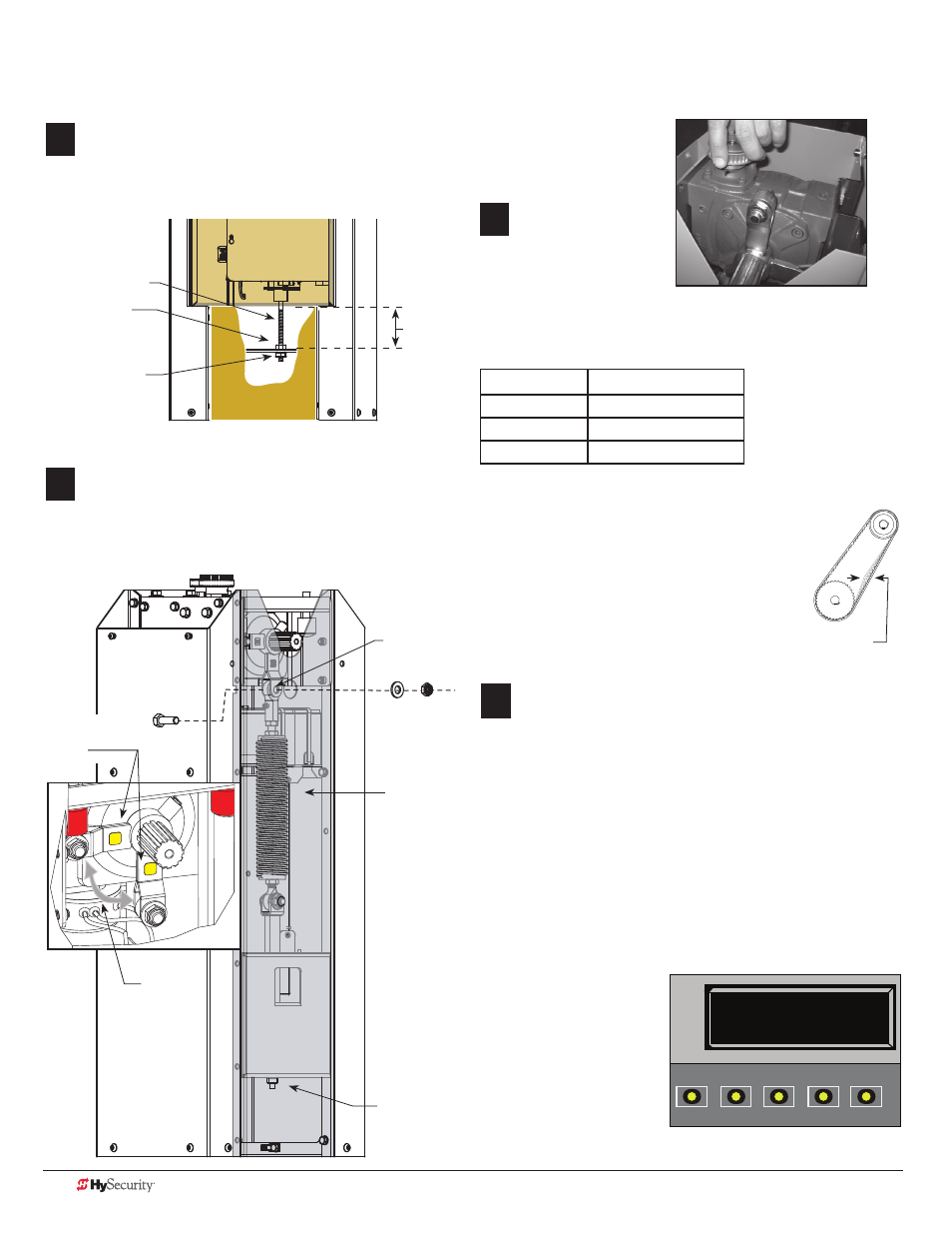
Remove spring tension. Use a crescent wrench (or 12 point
ratchet) to remove the square base nut and washer.
NOTE: You do not need to loosen the nut on the top of the
bracket. It helps keep the spring tension at factory settings.
Square top nut
Square base nut
All thread rod
12
8
Swap physical stop lever hardware. Use a 3/4-inch deep well
socket and box end wrench to remove the fasteners securing
the eyebolt. Then, loosen and remove the fasteners from
the other the physical stop lever and swap positions on the
physical stop levers.
Spring
Eyebolt
Physical stop
levers.
Square base nut
12
9
NOTE: For better access, you
can rotate the gear box to
reposition the physical stop
levers.
12
10
Reverse the steps found
on page 1.
Set Handing
Turn ON the DC power switch and set the handing
using the Smart DC Controller.
• Press MENU twice.
• Press and hold OPEN and RESET, and then release.
• Press NEXT until GATE HANDING appears.
• Press SELECT. SH blinks.
• Press NEXT to set the handing (Left or Right).
• To accept what is being displayed, press SELECT.
• To exit Menu mode, press RESET.
• Turn OFF the DC power switch.
• Install the breakaway bracket by aligning its splines with
the gear box.
• Assemble the arm,
apply power, and
re-learn limits.
• Finish the site
installation.
SH R (RIGHT)
GATE HANDING
OPEN
CLOSE
STOP
MENU
RESET
PREV
NEXT
SELECT
L
R
Swap
locations
(Remove/
Replace
fasteners
and
eyebolt.)
• Insert the all thread and
re-attach the base nut.
• Tighten the two base nuts to the required
“H” dimension. See chart.
Arm Length Spring Setting (H)
11 - 12 ft (3.6 m) 3.5 inches (89 mm)
12 - 13 ft (4 m)
3 inches (76 mm)
13 - 14 ft (4.3 m) 2.5 inches (63 mm)
StrongArmPark DC 14
NOTE: If the arm length is less than 11 ft (3.3 m), disconnect
the spring from the physical stop lever.
H
• Replace the motor and reconnect the 3 wire leads.
• Replace the drive belt and adjust the tension by
sliding the motor plate and tightening its 4 bolts.
• Replace the physical stop bracket removed in
step 3.
• Replace the drive belt cover.
1/16 to 1/8-inch
(1.6 to 3.2 mm)