Onnecting, Ccessory, Evices – Controlled Products Systems Group STRONGARMPARK DC 10 User Manual
Page 46: A device input • a common bus terminal (com)
4-6
D0536 Rev. B
StrongArmPark DC: Programming & Operations Manual
www.hysecurity.com
C
onneCtIng
a
CCessorY
d
evICes
Devices, such as gate edge sensors and photoelectric beams, must be installed to protect against entrapment.
These secondary entrapment protection devices are required for the gate installation to be in compliance with UL
325 Safety Standards. Most Crash gates are site-specific when it comes to safety standard compliance, and power
requirements fall under UL 508A. Always check your local area codes and comply with all regulations.
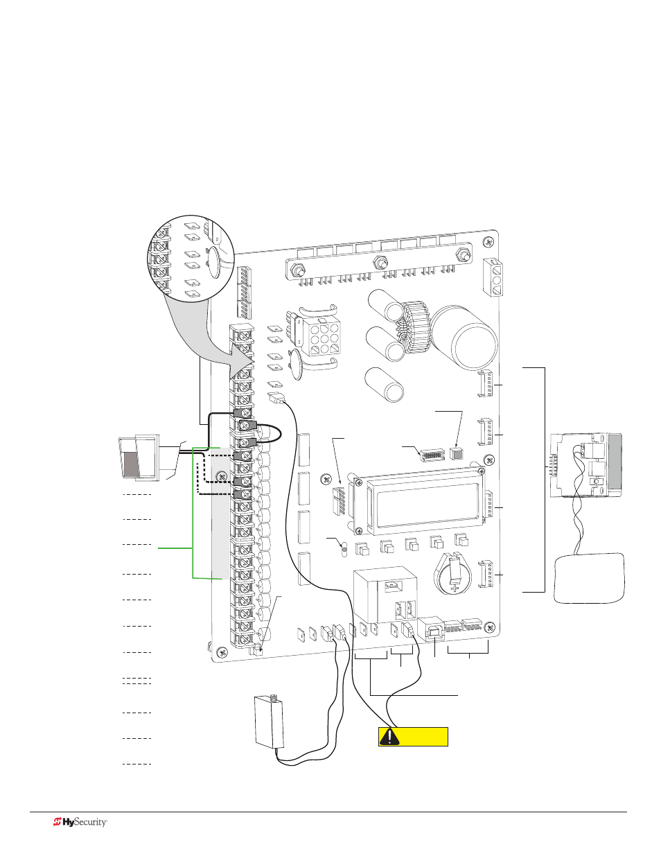
Standard accessory (entrapment and loop wire) connections are shown in the following illustration. All accessories
require a minimum of two connections:
• a device input
• a Common Bus Terminal (COM)
COM
COM
COM
COM
COM
COM
COM
COM
STOP
OPEN
RADIO
CLOSE
OPEN
OPEN
PARTIAL
EYE
OPEN
EYE
CLOSE
EXIT
LOOP
BLOCK
EXIT
IN OBS
LOOP
OUT OBS
LOOP
CENTER
LOOP
EDGE
EYE
COM
+ 24 V
EMERG
OPEN
SHOW
LEDs
RADIO OPTIONS
EDGE +24V OPE
N COM
DUAL GATE
COM
B
A
U
SE
R2
COM NO
DC
COMMON
TERMINALS
HY-5A
FREE EXIT
HY-5A
INSIDE LOOP
(Inner Arming
Loop)
HY-5A
OUTSIDE LOOP
(Outer Arming
Loop)
HY-5A
CENTER LOOP
RS-485
COMMUNICATION
USB PORT
USER RELAY 1
Electro-mechanical
USER RELAY 2
Solid state
24VDC
24VDC
24VAC
24VAC
12VDC
12VDC
VEHICLE LOOP
HY-5A
Access controls
Radio receiver
Connection for Dual (Master/Second or Sally Port)
or Sequenced gate systems.
(Ex. Card reader, keypad)
Red LED
heart
beat
indicates
processor is
working.
Multi-colored LED
indicates power and gate
status.
RS-232
Press button to light
active inputs.
Ethernet
expansion
24VDC
24VDC
24VAC
24VAC
12VDC
12VDC
CAUTION
When using HySecurity barrier arm with LED lights,
connect wires to 12VDC and User Relay 2 (NO). If you
connect the wire lead to 24VDC, damage to the arm
lights will occur and void the Limited Warranty.
Three power
supplies (2 terminals
each)are available
for peripheral
connections:
24VAC, 24VDC & 12VDC
NOTE: Each power supply
(and its corresponding
terminals) can be used in
any combination to draw
the available 1A maximum.
TRANSIENT
USER
CLOSE
SPECIAL
USER
TENANT
USER
SPARE
EYE
CLOSE
EXIT
LOOP
BLOCK
EXIT
INNER
ARMING
OUTER
ARMING
Parking Site Use
The label for the
Smart DC Controller
accommodates
arming loops and
establishes which
open commands
need to be wired
for vehicle counts
(transient, special,
and tenant “user
types”).
The software
identifies the access
control inputs and
uses the arming
loops to control
relay and network
outputs.
NOTE: The most current software must be loaded on your Smart
DC Controller and the operator identified as OT 14 for the Parking
Site labeled inputs to be effective.