Nstalling, Tandard, Ehicle – Controlled Products Systems Group STRONGARMPARK DC 10 User Manual
Page 54: Etectors
4-14
D0536 Rev. B
StrongArmPark DC: Programming & Operations Manual
www.hysecurity.com
“Installer Menu: Table 2.” on page 3-7.
For example, CLD0 RUN MODE
CENTER LOOP SET controls the center loop detector.
9. Sensitivity is the only adjustment available on the detector itself. Generally,
sensitivity does not need to be increased unless the loop is large or there
are multiple loops connected to one detector.
NOTE: Do not exceed more than 200 square feet (61 square meters)
of loop area to one detector.
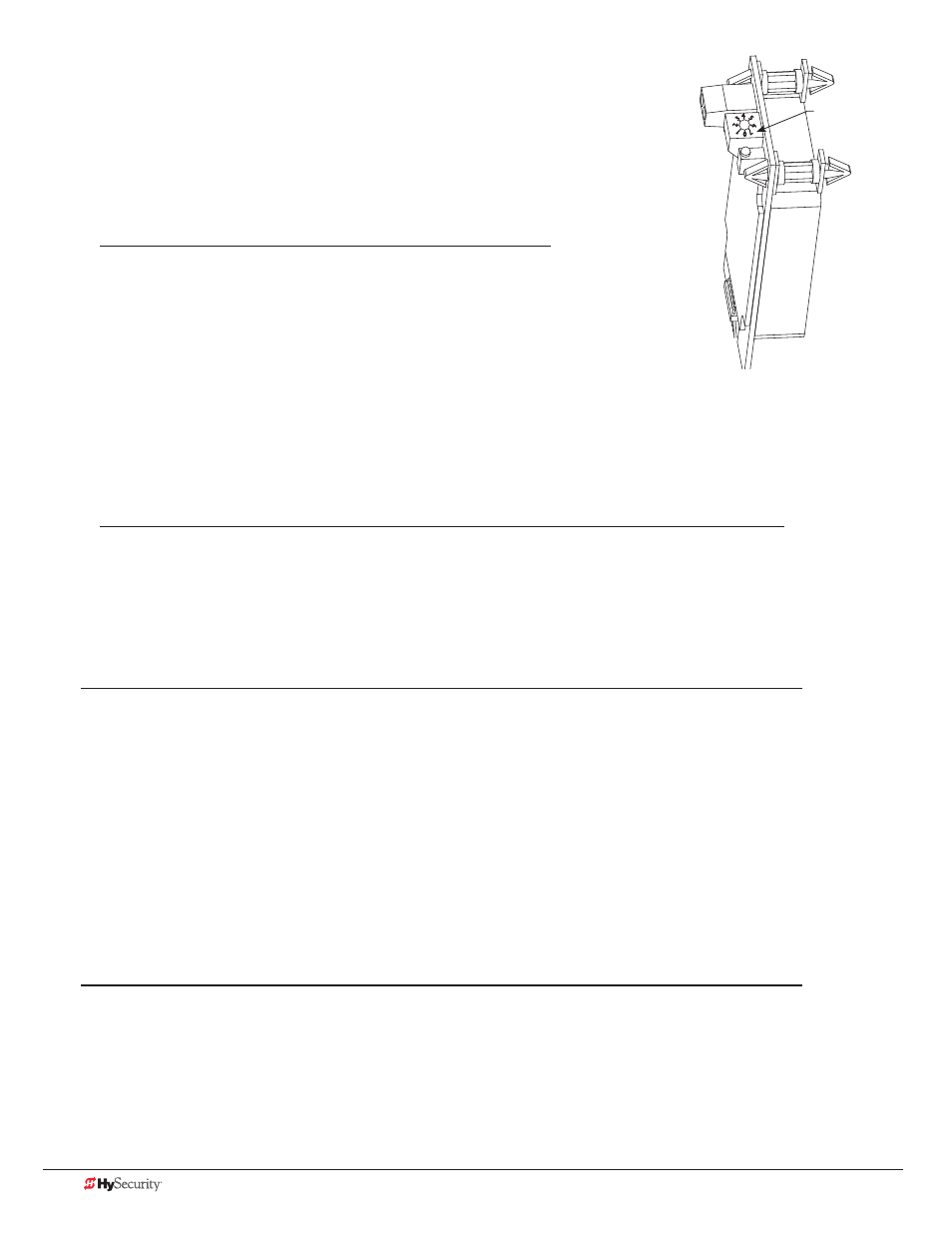
If required, adjust the sensitivity using the rotary dial.
The factory default setting is 1.
0 = Low with boost*
4 = Low without boost
1 = Normal with boost*
5 = Normal without boost
2 = Medium with boost*
6 = Medium without boost
3 = High with boost*
7 = High without boost
NOTE: *A boost feature is applied for settings 0 through 3. Boost increases the sensitivity during a call and is useful
for maintaining continuous detection if the signal becomes weak (such as with tractor-trailer trucks). Sensitivity set-
tings 4 through 7 are the same as 0 through 3, but without the boost feature.
10. Set the loop configuration in the Installer Menu. Display settings include, DT, CR, CB, CP, EB, OR, and IR.
11. Set the vehicle detector logic (DL).
NOTE: The outside and inside Obstruction Loop Detectors are factory configured to fully re-open the gate as a
default setting. In the Installer Menu, each detector can individually be set so that when the gate is closing there
is only a pause if triggered. To change the setting, go to the menu OR or IR item and set to 0.
I
nstallIng
s
tandard
11-p
In
B
ox
t
Ype
v
eHICle
d
eteCtors
If standard 11-pin box type vehicle detectors are to be used, perform the following procedure.
If there is sufficient space, install the sockets in the control box; if not, then install them in a separate external
housing. Carefully consider your peripheral connections. Any peripheral device required for safe gate operation
should be attached 24VDC in case of an AC power outage.
NOTE: Box detectors with relays require five times more power than HY-5A detectors. One HY-5A detector
draws about 0.005A.
1. Connect 24 Volt power to the detector. Connect Pin No. 1 to a 24VAC or 24VDC terminal and Pin No. 2 to
common.
2. Connect output Pin No. 6 to the Common Bus and output Pin No. 5 to one of the four detector terminal
inputs (depending upon the detector function required) on the Smart DC Controller.
1
2
3 4 56
70
Sensitivity dial