Able – Controlled Products Systems Group STRONGARMPARK DC 10 User Manual
Page 30
3-4
D0536 Rev. B
StrongArmPark DC: Programming & Operations Manual
www.hysecurity.com
u
ser
m
enu
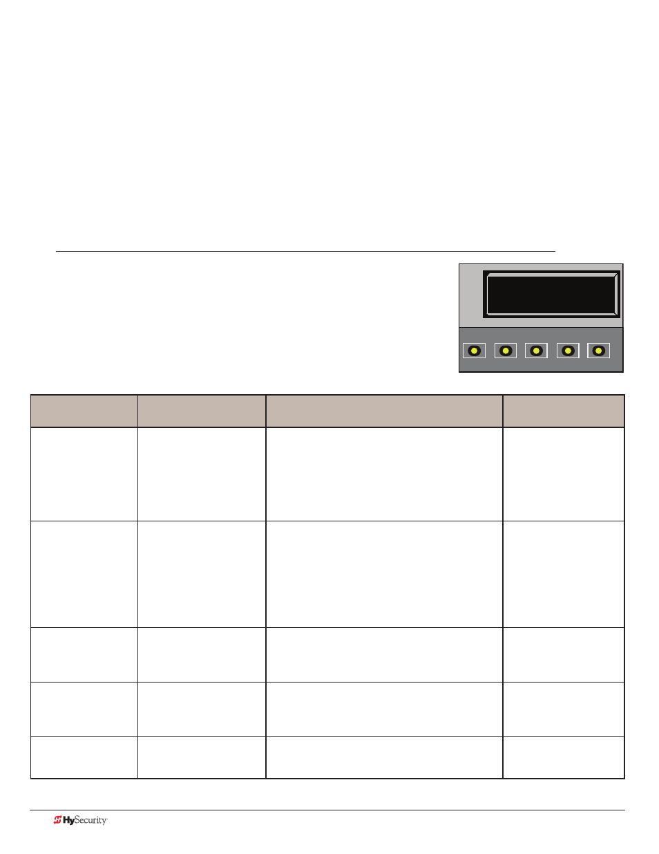
The User Menu consists of several items which can be modified using the Smart DC Controller keypad.
Access:
Pressing the MENU button, at one of the static Run Mode displays, causes the operator status displays to scroll
past, stop and display the first user menu item.
When the Close Timer (or Hold to Close “HC”) display appears, it means you have accessed the User Menu. The
Close Timer display is the first in a cyclical series of User Menu displays.
NOTE: To access the User Menu, the operator must be in Run Mode. To bypass the operator status displays, press
the Menu button a second time.
Use the navigational buttons, Select, Next, and Previous to change or view
the menu functions. Table 1 describes the User Menu items and supplies the
factory defaults. (Factory default settings shown in bold.)
u
ser
m
enu
: t
aBle
1.
User Menu
Setting Options
Menu Tasks & Explanations
SDC Wire
Connections
CT 0 (OFF)
Close Timer
0 = Timer disabled (OFF)
1 second to 99 seconds
The Close Timer assigns how many seconds before
the open gate initiates closure.
Keep the setting at 0 if a hard-wired, push-button
control device is being used. Refer HC.
NOTE: When the Hold to Close is set to 1, the Close
Timer display does not appear and HC1 becomes
the User Menu entry display.
Not applicable (N/A)
HC 0 (OFF)
Hold to Close
0 = off
1 = on
Set to 0 to produce an gate closure when a
momentary signal is transmitted.
Set to 1 if a constant hold to close signal, such as
a push button control, is being used. A setting of
1 also deactivates the automatic close timer and
causes its menu to disappear. The Hold to Close
replaces the Close Timer display as the User Menu
entry display.
COM
Close
HO 0 (OFF)
Hold to Open
0 = off
1 = on
Similar to Hold to Close, but configures the Open
inputs for a constant-hold function.
Set to 1, a constant hold to open signal, such as a
push button control, must be in use.
COM
Open
AP 0 AC LOSS
UPS FAIL OPEN
0 = UPS FAIL OPEN
1 = UPS FAIL CLOSE
2 = AUTO OPEN
3 = NO CLOSE TIMER
The setting configures how the gate functions when
AC power fails.
COM
RO 0 (OFF)
Radio Open/Close
0 = off
1 = on
A setting of zero, configures radio input for open
only. Setting 1 adds the capability for radio input to
close the gate, but only when it is fully open.
COM
RADIO Open
CT 0 (OFF)
CLOSE TIMER
OPEN
CLOSE
STOP
MENU
RESET
PREV
NEXT
SELECT