Connecting dc power, Turning the power switch on – Controlled Products Systems Group STRONGARMPARK DC 10 User Manual
Page 25
www.hysecurity.com
Power
D0536 Rev. B
2-5
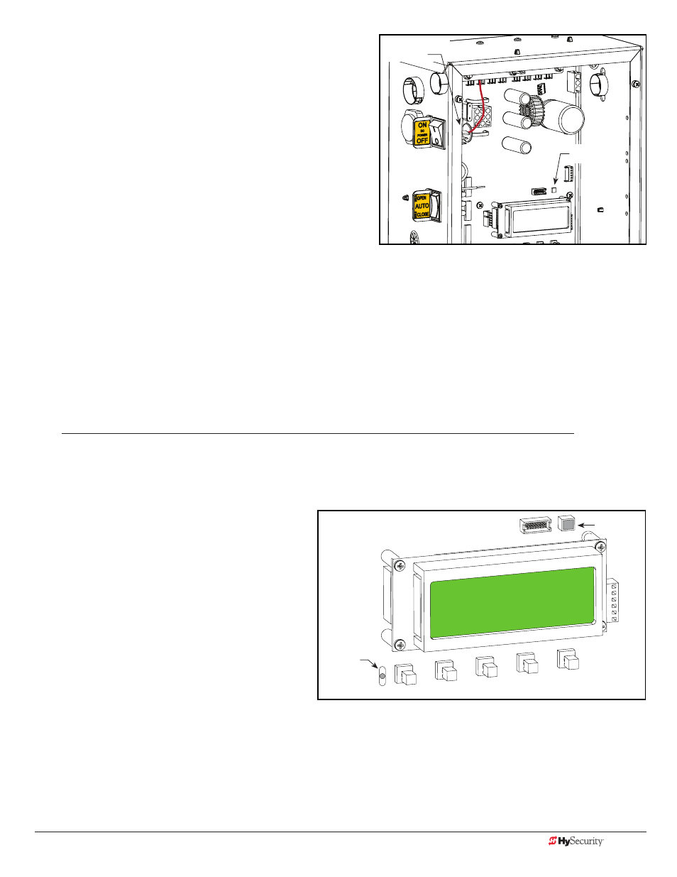
Connecting DC Power
To connect the DC power:
1. Turn off the DC and AC power switches.
2. Slide the plastic cover off the control box.
3. Attach the red spade connector to the battery terminal
on the DC power switch.
Turning the Power Switch ON
When both DC and AC power switches are turned ON:
• The barrier arm travels open and initiates a target search.
StrongArmPark DC senses the arm position and establishes its open and close limits. No physical limit switches
exist. Limits are automatically learned and remain intact even if AC power is lost and the batteries are fully drained.
The only exception occurs when factory defaults are reinstated, or the Smart DC Controller is replaced. For more
information about Learn Limits and Menu modes, refer to “Display & Menu Options” on page 3-1.
• A green status LED appears on the Smart DC Controller and remains static. The status light appears above the
display and indicates that the processor is receiving power.
NOTE: The Smart DC Controller can be powered when either switch is turned on. However, the operator is a DC-
powered unit and runs on its batteries. If the DC power switch is off, the operator will not function (even though
the AC power switch is on). When the operator is connected to AC power and the both AC and DC power
switches are turned on, the charge level of the battery is being monitored and maintained. On a solar-powered
operator, the AC power switch connects and disconnects the DC power from the solar panels.
The flashing red indicator light next to the OPEN button on the Smart DC Controller is considered the heart beat
of the system. It indicates that the electronics board is receiving power. When AC power is lost, the rate of
flashing slows down. Another indicator light, above the display, is multi-colored and corresponds to the action
that the operator is performing:
• Green - the operator is stopped.
• Flashing yellow - the operator is running.
• Red - the operator has experienced an error.
• Not lit - AC power is lost. Pressing the SHOW
LEDs button indicates which inputs, if any, are
active. Refer to Figure 4-2 for the SHOW LEDs
location on the board.
PREV
OPEN
NEXT
SELECT
CLOSE
STOP
MENU
RESET
Red spade
connector
Status light
Red LED flashes
indicating
processor is
working.
Green LED