Nstaller, Able – Controlled Products Systems Group STRONGARMPARK DC 10 User Manual
Page 33
www.hysecurity.com
Display Menu
D0536 Rev. B
3-7
I
nstaller
m
enu
: t
aBle
2.
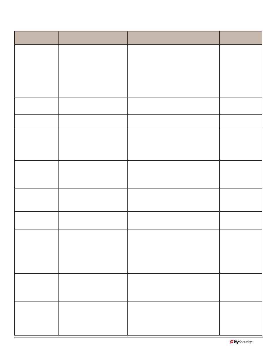
Installer Menu
Setting Options
Menu Tasks & Explanations
SDC Wire
Connections
OT 0
Set Operator Type
0 = operator type
12 = SwingSmart DC 20 & DCS 20
Solar
14 = StrongArmPark DC 10 & DC14
DCS 10 Solar & DCS 14 Solar
15 = SlideSmart DC 15 &
DCS 15 Solar
16 = SlideSmart DC 10F &
DCS 10F Solar
Select the appropriate number for the operator.
NOTE: This menu item only appears if the Smart
DC Controller is being replaced.
CAUTION: If you are replacing an SDC board,
remember to transfer the operator’s menu
settings from the existing board to the
replacement board. Refer to the installation
instructions that accompany the replacement
SDC board.
Not applicable (N/A)
MN 0
Model Number
0 = model type unknown
1 = Model 10
2 = Model 14
Select the type of StrongArmPark DC model
used at the site. NOTE: This menu item only
appears when you set the OT (operator type).
N/A
LL 0 (OFF)
Learn Limit Reset
0 = Normal setting
1 = Erases learned limit positions
Set to option 1, the system resets to accommo-
date for relearning limits.
N/A
UC 0
Usage Class
0 = gate disabled
1 = Family dwelling (1 to 4 units)
2 = Multi-family & commercial
3 = Light industrial*
4 = Industrial/guarded secure*
*Not serving the general public
Set the UL usage class. The installer must set the
usage class for the operator to function.
See “Identifying Gate Operator Category and
Usage Class” on page Safety-6.
NOTE: The usage class setting does not appear
on StrongArmPark DC and Crash products.
N/A
SH 0
Gate Handing
0 = gate disabled
R = viewed from the secure side, the
arm lifts right to open
L = viewed from the secure side, the
arm lifts left to open
The handing determines which way the gate
opens as you view it from the front access panel.
NOTE: StrongArmPark DC is factory configured
for left handing.
N/A
OS 1
Open Speed
DC10
DC14
1 = 2.5 seconds 1 = 3.5 seconds
2 = 2.0 seconds
2 = 3.0 seconds
3 = 1.5 seconds
3 = 2.5 seconds
Adjust how quickly the barrier arm opens.
CS 1
Close Speed
1 = 2.5 seconds 1 = 3.5 seconds
2 = 2.0 seconds
2 = 3.0 seconds
3 = 1.5 seconds
3 = 2.5 seconds
Adjust how quickly the barrier arm closes.
FD 0 (OFF)
Load Factory Defaults
0 = user settings
1 = reload factory settings
Select setting 1 to return the operator to factory
defaults which globally restores all menu settings
back to new operator status.
NOTICE: If factory defaults are restored, any
customized menu settings will need to be
reprogrammed. Before loading factory defaults,
you can save your customized menu settings
using a PC laptop & S.T.A.R.T.
N/A
DG 0 (OFF)
Dual Gate
0 = solo operator
1 = Slave unit
2 = Master unit
3 = Sally Port A
4 = Sally Port B
Establishes communication after wiring dual gate
connections between two operators in Master/
Second (Slave) or Sally Port site configurations.
This menu item appears if the sequenced gate
menu item SG is set at 0 (off).
Dual Gate COM
(Gate 1) to Dual Gate
COM (Gate 2)
A to A
B to B
SG 0 (OFF)
Sequenced Gate
0 = off
1 = Loop Layout/Site #1
2 = Loop Layout/Site #2
Establishes communication after wiring two or
more operators as sequenced gates.
This menu item only appears if the Dual Gate
menu item DG is set at 0 (solo operator).
NOTE: Access the User Menu in both operators
and set a Close Timer.
Connect Dual Gate
COM (Traffic Gate) to
Dual Gate COM
(Security Gate)
A to A
B to B