Elays, Rogramming, Rocedure – Controlled Products Systems Group STRONGARMPARK DC 10 User Manual
Page 47
www.hysecurity.com
SDC Inputs & Wiring
D0536 Rev. B
4-7
u
ser
r
elaYs
- p
rogrammIng
p
roCedure
The Smart DC Controller is able to interface with many types of external devices through the use of
programmable output relays: one mechanical relay (User 1) and one solid state relay (User 2) which is used most
often for connection to flashing devices.
NOTE: For StrongArmPark DC, an extended relay module option provides 8 additional mechanical relay connec-
tions. In the chart below, you use Relay 3 Logic through Relay 10 Logic for wire connections.
All of the user relay functions identified and described in the table below are accessible in the Installer Menu
selections.
NOTE: A setting of zero disables a user relay. The user relays will operate normally to 18VDC. Below 18VDC, alert
notification occurs. On StrongArmPark DC the R2 RELAY 2 LOGIC is recommended for LED arm lights.
Use the SDC buttons to program the user relays according to the following steps:
1. Select the relay you wish to use through the “Installer Menu: Table 2.” on page 3-7.
For example: R1, RELAY 1 LOGIC.
2. Select the appropriate function (1 through 39) by changing the display to the associated number listed
in the table. Use the Select, Next and Previous buttons to make your selection. See “Menu Mode
Navigation” on page 3-2.
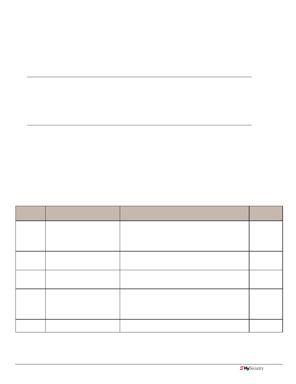
Programmable User Relays: Table 4
Relay No.
Name
Description
Wire
Connection
1
Close limit output
Output can be used as an interlock signal to another operator’s
interlock input, or simply to indicate that the gate is secure. The
relay is “off” when the gate is closed. The relay energizes when
the fully-closed limit is released. (Any open command energizes
the relay.)
Relay 1
2
Close limit pulse output
Used in a sequenced system to command a second operator
to close. Generates a brief pulsed output that occurs when the
close limit is triggered.
Relay 1
3
Open limit output
Indicates a full-open position. This output becomes active when
an open-limit is triggered and deactivates when the open-limit is
released or a close command is received.
Relay 1
4
Open limit pulse output
Used in a sequenced system to command a second operator
to open. Generates a brief pulsed output that occurs when the
open limit is triggered. An additional pulse is also generated
with any new open command even when the gate is already
fully-opened.
Relay 1
5
Warn before/during operate output
Controls an external warning device. This output operates at the
same time as the internal warn before operate buzzer.
Relay 1