Color cameras, Description of the data path, Figure 33: block diagram color camera – ALLIED Vision Technologies Marlin F-201 User Manual
Page 66: Marlin technical manual v2.4.0
Description of the data path
MARLIN Technical Manual V2.4.0
66
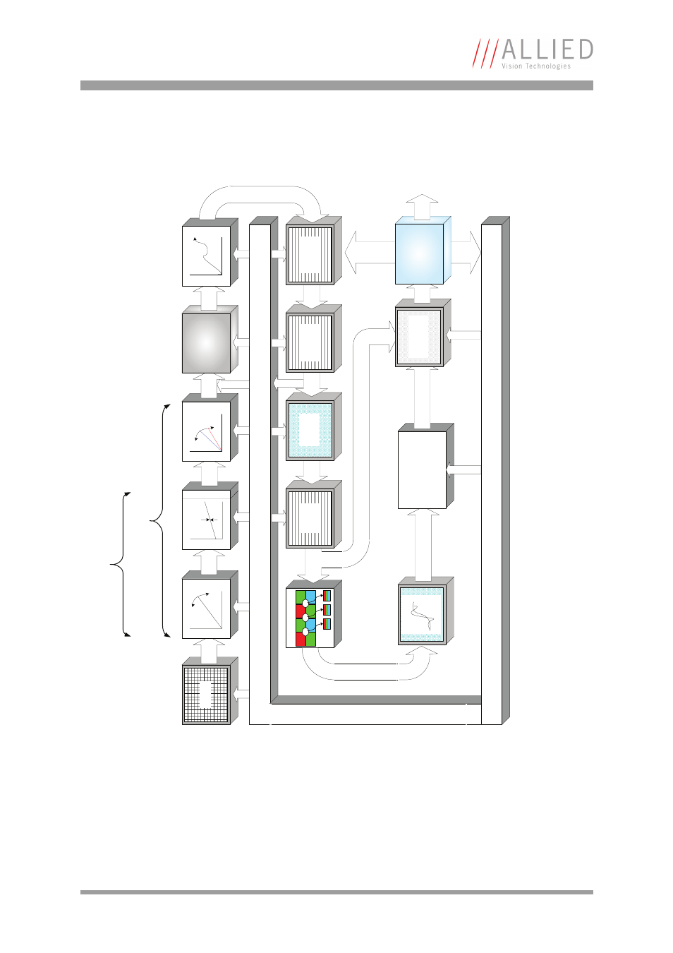
Color cameras
Figure 33: Block diagram color camera
Sensor
Anal
og
Camera Control
HiRose I/O
RS232
De-Bayering
R1
G1
R2
G2
G3
B1
G4
B2
P
1
P
2
P
3
CMOS:
Integrated in the sensor
(ADC:
10 bit
)
CCD: Integrated in Analog
Fr
ont End (
A
FE)
8 Bit
Test-Pattern
Auto-Data
10 Bit
8 Bit
F
ram
e-
Memory
8/10
Bit*
Graphics
Overlay
10 Bi
t
Horizontal
Mirror
10 Bit
Horizontal
Masking
Sharpness
Camera Control
Gain
Analog
Offset
CCD:
12 Bit
White Balance
CCD
:
12 Bi
t
Shading
Correction
A
D
C
10 Bi
t
LUT
10 Bit (LUT off)
8 Bit (LUT on)
10 Bit
Multiple Color
Operations
(RGB->YUV, Hue,
Saturation)
Params
8 Bi
t
RAW-Mode
MUX
8 Bit
IEEE-1394
Interface
13
94
a
This manual is related to the following products: