Input/output pin control, Io_inp_ctrl 1-2 – ALLIED Vision Technologies Marlin F-201 User Manual
Page 53
Camera interfaces
MARLIN Technical Manual V2.4.0
53
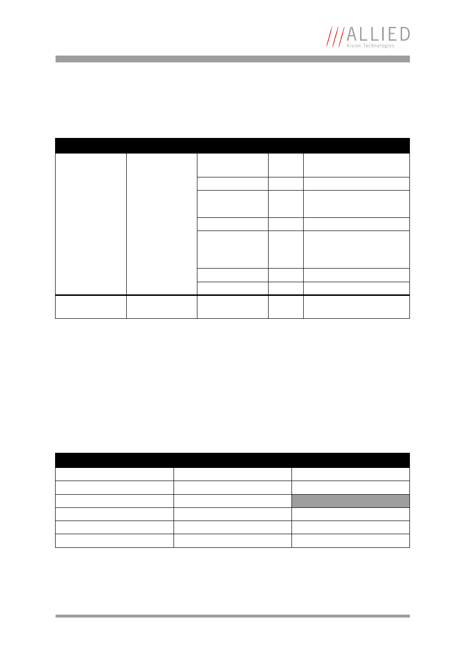
Input/output pin control
All input and output signals running over the camera I/O connector are con-
trolled by an advanced feature register.
IO_INP_CTRL 1-2
The Polarity flag determines whether the input is low active (0) or high
active (1). The input mode can be seen in the following table. The PinState
flag is used to query the current status of the input.
Register
Name
Field
Bit
Description
0xF1000300
IO_INP_CTRL1
Presence_Inq
[0]
Indicates presence of this
feature (read only)
---
[1..6]
Polarity
[7]
0: low active
1: high active
---
[8..10]
Reserved
InputMode
[11..15] Mode
see
---
[16..30] Reserved
PinState
[31]
RD: Current state of pin
0xF1000304
IO_INP_CTRL2
Same as
IO_INP_CTRL1
Table 18: Advanced register: Input control
L
•
For inputs the PinState bit refers to the inverted out-
put side of the optical coupler. This signals that an
open input sets the PinState bit to 1.
ID
Mode
Default
0x00
Off
0x01
Reserved
0x02
Trigger input
Input 1
0x03
Reserved
0x06..0x0F
Reserved
0x10..0x1F
Reserved
Table 19: Input routing