Franklin Fueling Systems TS-DTU Data Transfer Unit Dispenser Retrofit Manual User Manual
Page 9
9
Gilbarco Advantage Narrow Frame - DTU Installation
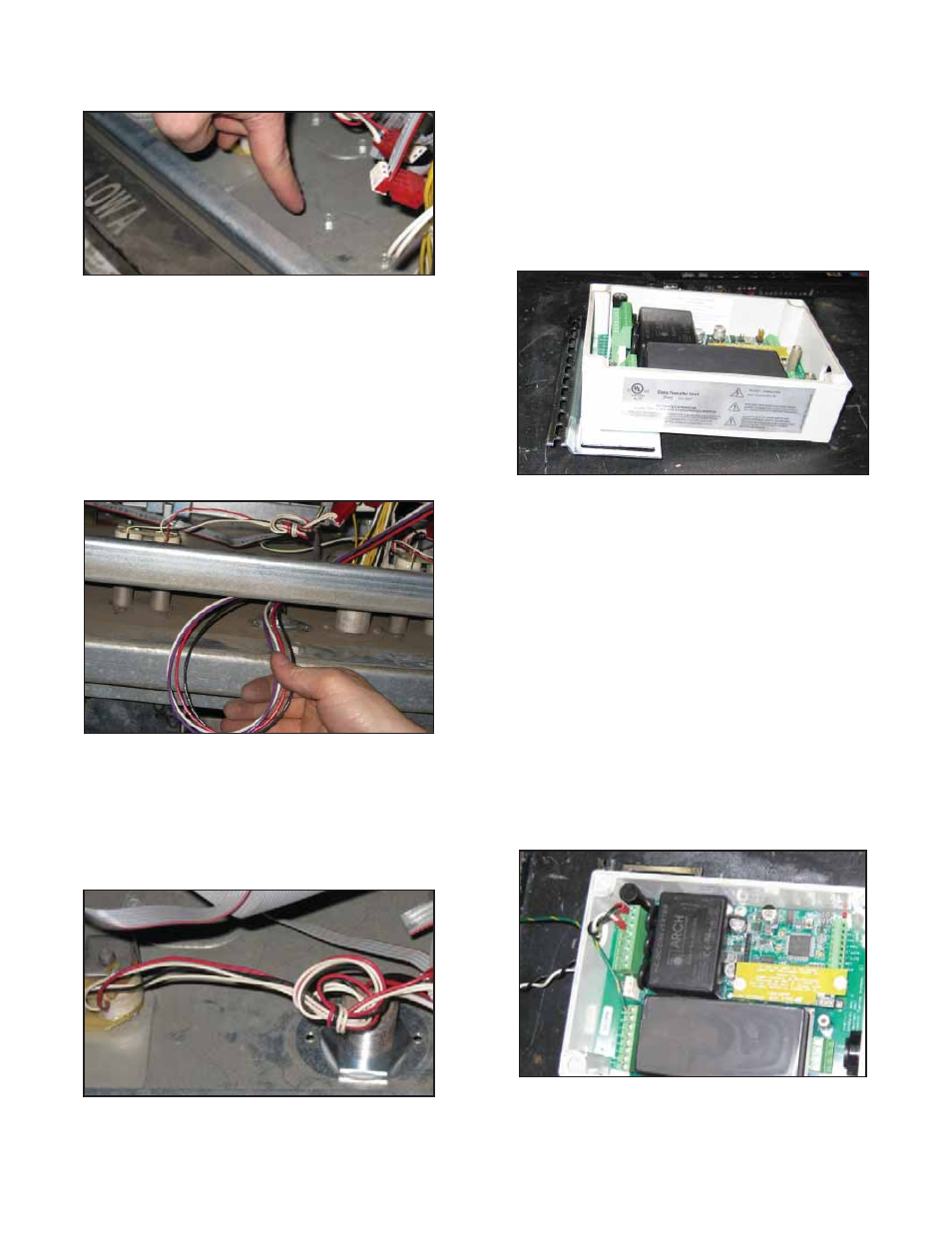
9. Remove two screws from upper air gap knock-out
cover and remove. Discard cover but keep screws
for reuse.
Figure 7: Remove Screws
10. Remove two screws from lower air gap knockout
cover and remove. Discard cover and screws.
11. Remove lower door from side A of dispenser using
key lock on right side of door. Save door for future
reassembly
12. Find potted nipple assembly, 131610. Remove all
washers and nuts and set aside.
13. Pull wires from top side of potted nipple assembly
through dispenser hydraulics enclosure up through
opening in lower air gap knock-out.
Figure 8: Potted Conduit wires
14. Attach one nut and washer onto the potted nipple
assembly before pushing wires up through electrical
enclosure.
15. Pull wires and then nipple assembly up into electronics
enclosure. Fit washer and nut over wires and tighten
nut securely in place, as shown in Figure 9.
Figure 9: Potted Nipple Installed
16. Reattach air gap shield using screws previously
retained in step 8.
17. Reinstall the screws previously retain in step 9.
These screws seal the holes left behind by the air
gap knockout.
18. Find TS-DTU / P kit and remove brackets, DTU,
and hardware from box.
19. Remove cover from DTU.
20. Install mounting bracket to DTU with two screws,
nuts and washers from hardware provided with
DTU as described in the General Information
section. Ensure that bracket is installed on correct
side as shown.
Figure 10: Mounting Bracket on DTU
21. Remove two screws from IS wiring cover inside
the DTU and remove cover. Retain cover and
screws for reassembly
22. Find the 90 degree fi tting from IS wiring kit,
020-1513. Remove nut from 90 degree fi tting.
Attach fi tting to opening nearest IS wiring terminal
block of DTU using nut previously removed.
23. Find power harness kit part number 600-0168.
Find the Gilbarco Advantage power harness and
ground with ring terminal as shown in fi gure 4 of
the Parts List.
24. Put wiring harness end with crimp connector
through opening in DTU nearest terminal block
J1. Attach white lead to terminal block position
labeled NEUTRAL and black lead to terminal
block position labeled L1 on terminal block J1 of
DTU. Attach ground wire to terminal block position
labeled GND of J2 on DTU.
Figure 11: DTU Power Connections
25. Move DTU assembly to dispenser nearest
intended mounting location