Franklin Fueling Systems TS-DTU Data Transfer Unit Dispenser Retrofit Manual User Manual
Page 27
Wayne Ovation - DTU Installation
27
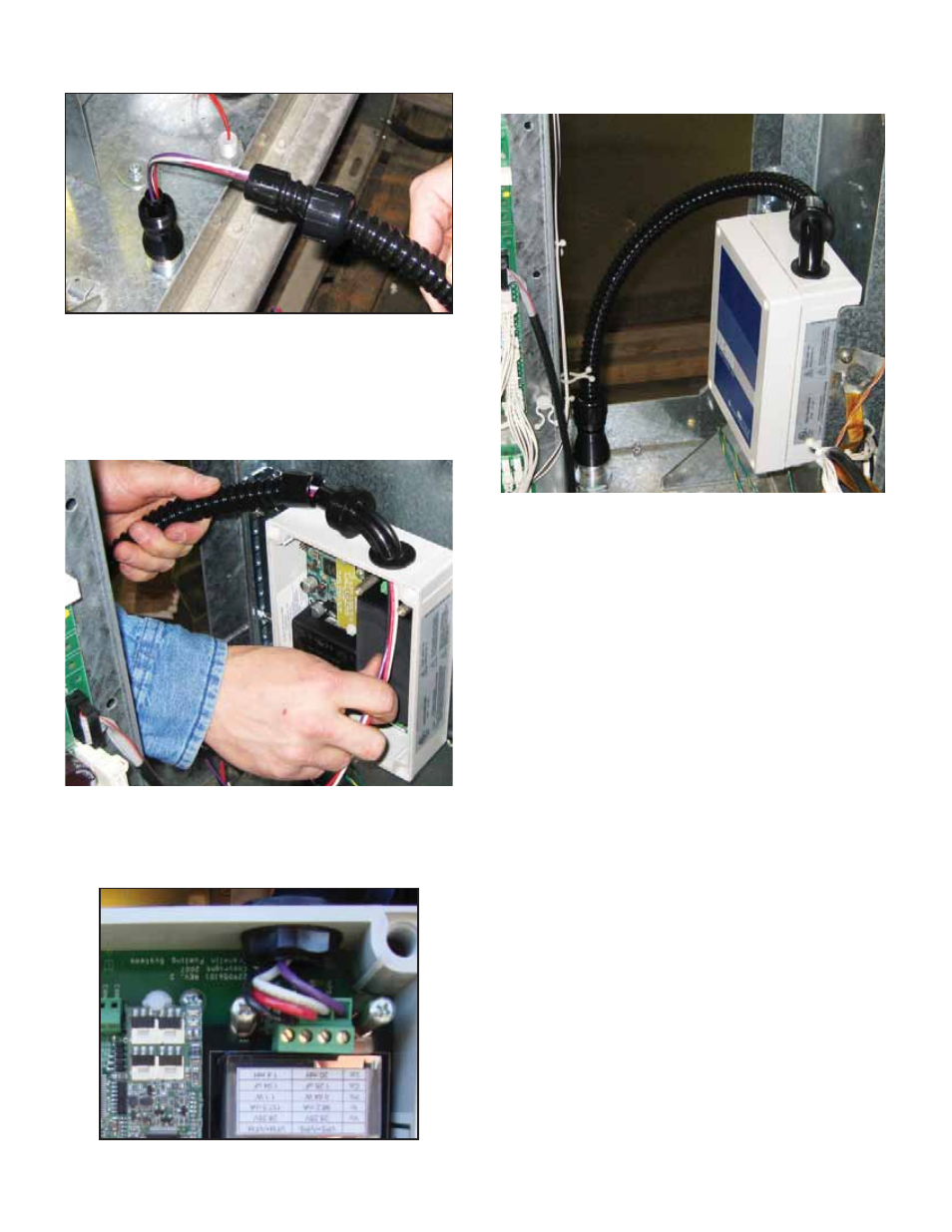
29. Push bushing onto end of fl exible conduit and
reattach to straight fi tting using nut.
Figure 14: Attach Flexible Conduit to Potted Nipple
30. Remove bushing and nut from 90-degree fi tting on
DTU and pull wiring and fl exible conduit through.
31. Pull wires through 90-degree fi tting and pull into
the DTU enclosure.
32. Use nut and attach fl exible conduit to 90-degree
fi tting.
Figure 15: Attach Flexible Conduit to 90-Degree Fitting
33. Cut excess wire inside DTU allowing a length of 2”
for terminal block wiring. Strip insulation 3/8” from
end of wire. Attach wires to DTU terminal block as
follows
Figure 16: Terminal Block Wiring
34. Reinstall barrier cover using screws removed in
step 24.
35. Replace DTU cover.
Figure 17: Attach Cover to DTU
36. Find cable assembly extending from TS-VFM
vapor meter in dispenser hydraulics enclosure.
37. Locate wiring from previously installed potted
nipple assembly inside hydraulics enclosure.
38. Find two-wire splice connector kits. Inside hydraulics
enclosure connect black wire from potted nipple
assembly to black wire from TS-VFM fl ow meter by
placing each lead into an opening in the wire splice
connector and push fi tting closed to lock.
39. Find cable extending from TS-VPS inside
hydraulics enclosure. Cut yellow and blue leads
from end of cable.
40. Find purple and white wires from potted nipple
assembly in hydraulics enclosure. Strip wiring
insulation at end 3/8”.
41. Using wire nuts provided with kit, attach purple
wire from potted nipple assembly to black wire of
TS-VPS and attach white wire from potted nipple
assembly to white wire of the TS-VPS.
42. Replace lower hydraulics door using two screws
on door.
43. Close dispenser doors on each side of the unit and
fi rmly attach with two screws located in each door.