Wayne vista 2 – Franklin Fueling Systems TS-DTU Data Transfer Unit Dispenser Retrofit Manual User Manual
Page 32
32
Wayne Vista 2 - DTU Installation
Wayne Vista 2
This section illustrates the basic components needed
to retrofi t a TS-DTU module into an existing dispenser.
This system can be installed in any “Non-Vapor or Vapor
Ready” dispenser including dispensers with existing
“Balance” or “VacAssist” piping.
1. Using key-lock, remove lower door on B side of
dispenser. B side of the dispenser does not have
dispenser marking at the base.
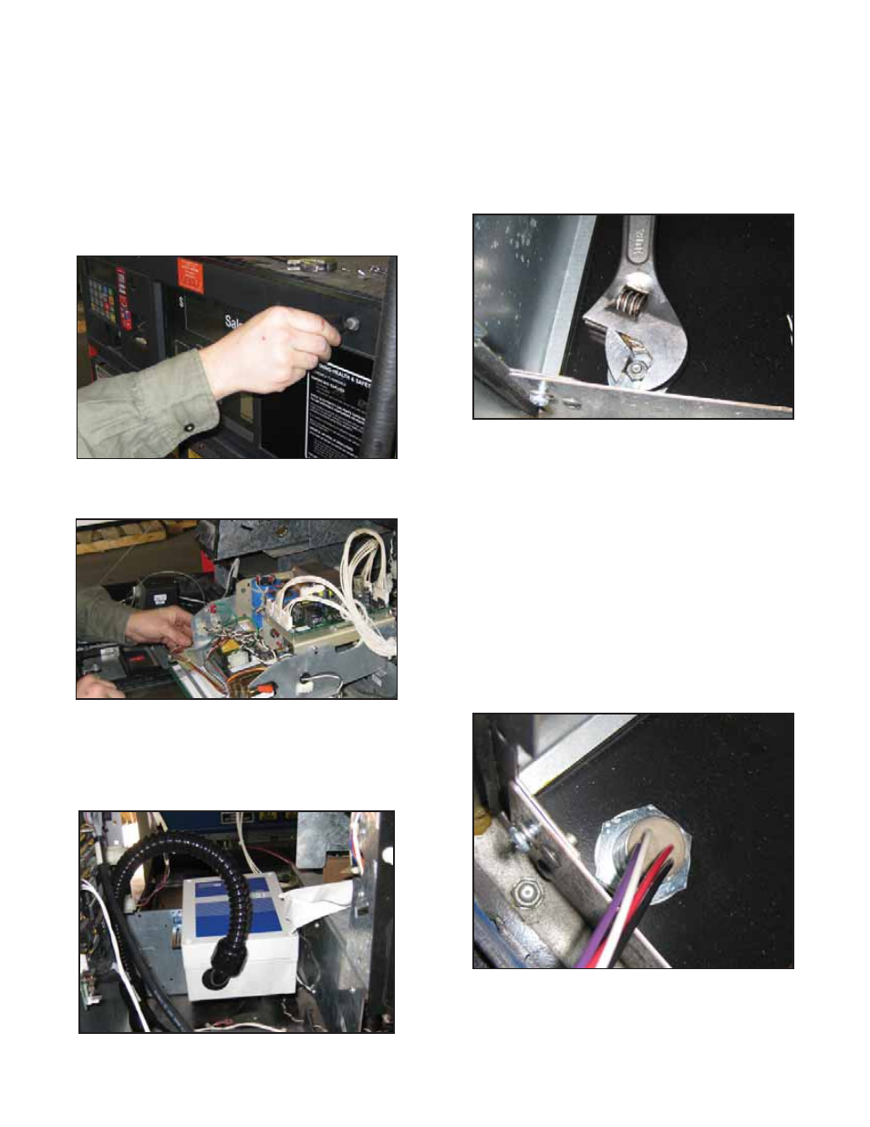
2. Open upper dispenser door on both sides by
loosening two screws on each door.
Figure 1: Open Upper Dispenser Door
3. On “B” side, remove two screws holding display
assembly and carefully lower into resting position.
Figure 2: Carefully Lower Door
4. DTU will be installed in the location shown below.
(The DTU will not be installed until step 21)
Examine the bottom of the electrical enclosure
to determine location of unused hole plugs and
choose the appropriate side of dispenser.
Figure 3: DTU Installed
Note: Hole plugs beneath plastic catch pans cannot be
used as there is not enough clearance to install
conduit fi ttings.
5. Remove lower dispenser door using key lock
closest to the hole plug chosen in step 2.
6. Using two wrenches, remove nut from hole plug
found at the bottom of the electrical enclosure.
Remove bolt, nut, and washers and dispose of
them.
Figure 4: Remove Hole Plug
7. Find potted nipple assembly, 131610.
Open wire ties and unwind wiring.
8. Remove and dispose of rubber washer from
assembly.
9. Remove top nut from potted nipple and remove
nut and one washer by pulling over wire leads.
Keep nut and washer for future use.
10. Pull top wires of potted nipple assembly from the
hydraulics enclosure to the electrical enclosure.
Ensure that wiring is not damaged by sharp edges.
11. Pull top of potted nipple assembly through
opening in electrical enclosure. Route wires inside
electrical enclosure through washer and nut
retained in step 9. Attach potted nipple assembly
by tightening nut.
Figure 5: Potted Nipple Installed
12. Find reducer from IS conduit kit, 020-1513. From
electrical enclosure, pull wires from the potted
nipple assembly through ¾” opening of reducer and
attach reducer to the top of the nipple assembly.